Quick answer: Compression testing machines measure how much force a material or component can withstand before it deforms or fails under a squeezing load, and choosing the right one comes down to matching load capacity, accuracy class, and drive system to the material being tested. Hydraulic machines dominate high-force applications like concrete cylinders and steel rebar, where loads regularly exceed 300 kN, while electromechanical and servo-electric systems suit lower-force, precision-critical testing on plastics, foams, and composites. Getting the capacity, platen type, and calibration schedule wrong is the single most common cause of unreliable results.
A concrete cylinder that should hold 30 MPa but crumbles early, or a plastic component that passes lab testing and then fails in the field, often points back to the testing equipment rather than the material itself. Compression testing machines are only as reliable as their calibration, their platen alignment, and the match between machine capacity and specimen strength — get any one of those wrong and the data coming off the readout stops meaning what it's supposed to mean. Understanding what actually separates one compression tester from another, and which specification matters for which material, is the difference between a lab result that holds up and one that doesn't.
How Compression Testing Machines Actually Work
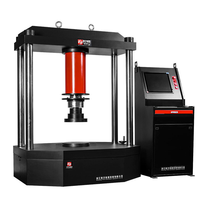
At its core, a compression testing machine places a specimen between two parallel platens and applies a steadily increasing force until the material deforms, yields, or fractures. The machine records force and displacement continuously throughout the test, generating a stress-strain curve that reveals compressive strength, yield point, and modulus of elasticity. What separates a reliable machine from an unreliable one is how precisely it can apply that load, hold it steady, and measure the specimen's response without introducing its own error into the data.
The Core Systems Every Machine Needs
- Load frame — the rigid structure that resists the reaction force without flexing; frame stiffness directly affects measurement accuracy
- Drive system — hydraulic piston or electric motor-driven screw, responsible for generating and controlling the compressive force
- Load cell — measures applied force, typically to accuracy class 1.0 or better per ISO 7500-1
- Platens — the contact surfaces that transmit load to the specimen; flat hardened steel for most materials, spherically seated for concrete cylinders
- Displacement measurement — crosshead encoders, compressometers, or LVDTs, depending on the precision required
Standards note: Compression testing typically requires lower measurement accuracy than tensile testing, simply because compression forces tend to be much higher in magnitude. Even so, ASTM C39 specifies a required loading rate accuracy of 0.25±0.05 MPa/s for concrete testing, and deviating from that rate can meaningfully skew the recorded strength value.
Hydraulic vs Electromechanical: Choosing the Right Drive System
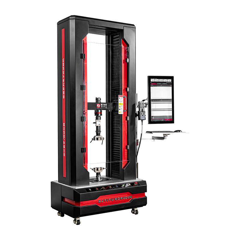
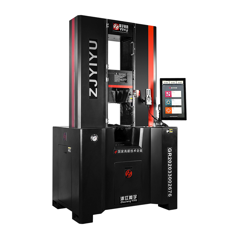
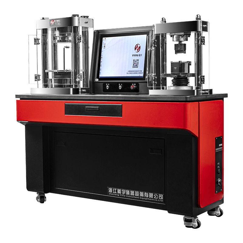
The single biggest decision in selecting a compression tester is the drive mechanism, and it comes down almost entirely to force requirements and the material being tested. Getting this wrong isn't just a performance issue — pushing an electromechanical machine past its intended force range can damage its bearings and gears over time, while a hydraulic machine used for delicate precision work sacrifices accuracy it doesn't need to sacrifice.
| Factor |
Hydraulic |
Electromechanical / Servo-Electric |
| Typical force range |
300 kN up to 3,000 kN+ |
Very low forces up to roughly 250–300 kN |
| Best suited materials |
Concrete, steel rebar, structural components |
Plastics, foams, composites, textiles |
| Precision and control |
High, but generally less fine than electromechanical |
Very high; excellent for R&D and modulus testing |
| Shock resistance |
Excellent — absorbs violent energy release at fracture |
Can suffer bearing/gear wear under repeated high-impact fracture |
| Running cost |
Higher, due to hydraulic fluid maintenance |
Lower, no fluid system to maintain |
| Typical upfront cost |
More economical for high-force capacity |
Higher cost as force capacity increases |
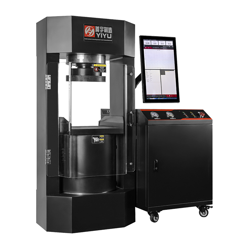
The practical rule of thumb: once a testing program regularly requires loads above 300 kN, hydraulic systems become both the more durable and more cost-effective choice. This is exactly why hydraulic machines are the standard for compression testing steel rebar, high-strength fasteners, concrete cylinders, and large structural members — materials that release substantial shock energy at the moment of failure. A construction materials lab evaluating concrete cylinder strength needs a hydraulic machine capable of applying massive loads, while a manufacturer testing an injection-molded plastic component is better served by an electromechanical machine for its precision and smooth force control.
When Servo-Electric Machines Make Sense
- Testing requires very fine, repeatable control over force application rate
- Specimens are fragile or low-strength (foams, thin polymers, packaging materials)
- Energy efficiency and lower operating cost are priorities
- R&D work needs precise displacement data for modulus calculations
Matching Load Capacity to the Material Being Tested
Undersizing a machine's capacity risks damaging the frame or load cell; oversizing wastes budget and can reduce measurement resolution at lower forces. The right approach is to calculate the expected failure load from the specimen's known or expected strength and cross-section, then select a machine with adequate safety margin above that figure.
880 kNrequired capacity for a 150mm concrete cylinder at 50 MPa strength
1,000 kNrecommended load cell selection to cover that specimen safely
±1.0%maximum load indication error for Class 1 accuracy per ISO 7500-1
That worked example is a useful template for any material: calculate the maximum expected force, then select equipment with meaningful headroom above it rather than equipment rated exactly at the anticipated failure load. Test space also needs the same careful calculation — required height equals the maximum specimen height plus the upper platen, lower platen, and roughly 50mm of working clearance. A 300mm concrete cylinder, for example, needs a minimum test space of about 400mm to accommodate the full assembly.
Platen Selection and Why It Changes Test Accuracy
Platens aren't a minor accessory — they're the interface through which every unit of force reaches the specimen, and the wrong platen type introduces error that no amount of load cell precision can correct. Two platen designs cover most applications, and picking between them depends entirely on the specimen geometry.
Spherically Seated Platens
- Used for concrete cylinders and similar specimens
- Accommodates minor specimen misalignment automatically
- Bearing should rotate freely — verify monthly
- Required under ASTM C39 and AASHTO T22
Flat Hardened-Steel Platens
- Standard for plastics, metals, and composites
- Hardness typically HRC 58–62 per ASTM E9
- Flatness tolerance of 0.025mm over entire surface
- Parallelism check: 0.05mm maximum across platen diameter
Common failure point: Misalignment in load application is one of the most frequently cited causes of inconsistent compression test results. Incorrect specimen centering, uneven platen surfaces, or frame misalignment can all skew data in ways that look like material variability but are actually equipment error.
Calibration and Maintenance That Protects Data Integrity
A compression testing machine's accuracy degrades gradually and often invisibly — sensor drift, platen wear, and hydraulic pressure inconsistencies build up over months of use without triggering an obvious failure. This makes scheduled calibration and maintenance a data-integrity issue, not just an equipment-longevity one.
Recommended Maintenance Cadence
- Daily — clean platen surfaces, verify emergency stop function, check hydraulic fluid level and look for leaks at actuator seals
- Weekly — lubricate ball screw and guide rails on electromechanical systems, clean load cell housing of dust or moisture, verify platen parallelism with a precision level
- Monthly — inspect spherically seated platen bearings for free rotation, check hydraulic hose connections for wear, verify smooth crosshead movement through the full stroke
- Annually — full load cell calibration against a certified reference standard, traceable to national measurement standards
Formal calibration involves placing a reference load cell or proving ring inside the frame and applying incremental loads — typically at 20%, 40%, 60%, 80%, and 100% of rated capacity — then comparing the machine's readings against the known reference values. Any deviation beyond the ±1.0% threshold for Class 1 accuracy needs correction before the machine returns to service. Most laboratory accreditation bodies expect this calibration to be performed at least once a year by a certified body, with full documentation maintained per ISO/IEC 17025.
ISO 7500-1 accuracy ASTM C39 / D695 / E9 Traceable calibration Spherical seating Class 1 load indication
Selecting a Machine for Your Application
Rather than starting from a brand or price point, the most reliable procurement process starts from the material and testing standard, then works backward to the machine specification that satisfies both.
| Material / Application |
Governing Standard |
Recommended Machine Type |
| Concrete cylinders and masonry units |
ASTM C39, C140, C1716, AASHTO T22 |
Hydraulic, spherically seated platens |
| Rigid plastics and polymers |
ASTM D695, ISO 604 |
Electromechanical or servo-electric |
| Metals and structural components |
ASTM E9 |
Hydraulic for high force, flat hardened platens |
| Aerospace composites |
ISO/EN/ASTM, Airbus AITM, Boeing BSS |
Electromechanical, modular 100–250 kN systems |
| Foams, packaging, textiles |
Varies by application |
Low-force electromechanical, fine control |
Practical Checklist Before Purchasing
- Confirm required load capacity with margin above the maximum expected specimen strength, not equal to it
- Verify compliance with the specific testing standard governing your material (ASTM C39, D695, E9, or equivalent)
- Match platen type to specimen geometry — spherically seated for concrete, flat hardened steel for most everything else
- Confirm the supplier provides traceable calibration certification per ISO 7500-1
- Calculate required test space based on maximum specimen height plus platen and clearance allowance
- Factor ongoing calibration and maintenance costs into total cost of ownership, not just the purchase price

 简体中文
简体中文
 English
 русский