Dynamic cone penetration testing has long been one of the most practical tools in geotechnical quality control. When field engineers send us their penetrometer logs, the question we hear most often is straightforward: how to calculate CBR from DCP test results without guesswork. The DCP is fast, economical, and remarkably repeatable, but the raw output—millimetres of penetration per blow—means little until it is converted into a California Bearing Ratio (CBR) value that pavement designers and site supervisors can act on.
In this guide, we walk through the calculation method step by step. We explain the DCP test, show how to record clean field data, introduce the standard conversion formula, and demonstrate the entire process with a worked example using realistic test readings.
Understanding the DCP Test
The dynamic cone penetrometer drives a steel cone into the ground using a sliding hammer. In the common ASTM D6951 configuration, an 8 kg hammer drops from a height of 575 mm onto an anvil, pushing a 60-degree cone with a 20 mm base diameter into the soil. Each blow advances the cone a certain distance. A soft, weak subgrade may advance 30 mm or more per blow, while a well-compacted gravelly layer may move only a few millimetres.
This penetration rate reflects the strength and stiffness of the soil. Engineers convert it into a Dynamic Penetration Index (DPI), expressed in millimetres per blow. The lower the DPI, the stronger the material. DPI is then correlated to CBR, which is the value most pavement design methods recognise.
Recording Field Data Correctly
Accurate CBR estimates begin with disciplined field recording. The procedure itself is simple, but small mistakes can shift the final result significantly. Follow this sequence:
- Place the penetrometer vertically on the prepared surface and record the initial reading on the scale.
- Raise the hammer to the specified drop height and release it to drive the cone into the soil.
- After each blow, read the new scale position and subtract the previous reading to obtain the penetration increment.
- Continue until the desired test depth is reached, or until the penetration rate becomes excessive for the equipment.
Most accepted procedures recommend discarding the first two or three blows. These initial readings include surface disturbance and seating effects. After seating the cone, start a fresh initial reading and record the following blows as the basis for calculation.
Calculating the Dynamic Penetration Index
Once the seating blows are complete, the DPI is simply the total measured penetration divided by the number of counted blows:
DPI = (Final reading after seating − Initial reading after seating) ÷ Number of blows counted
For example, if the initial reading after seating is 42 mm and, after seven blows, the scale shows 238 mm, the calculation is:
DPI = (238 − 42) ÷ 7 = 196 ÷ 7 = 28 mm/blow
Keep the unit in millimetres per blow. The conversion formulas discussed in the next section expect this unit; if your equipment scale is marked in inches, convert to millimetres before proceeding.
Converting DPI to CBR: Standard Formulas
The most widely used correlation in international pavement work comes from ASTM D6951:
CBR (field) = 292 ÷ DPI1.12
Some regions, particularly in South Asia, prefer the equivalent logarithmic form:
Log₁₀(CBR) = 2.48 − 1.057 × Log₁₀(DPI)
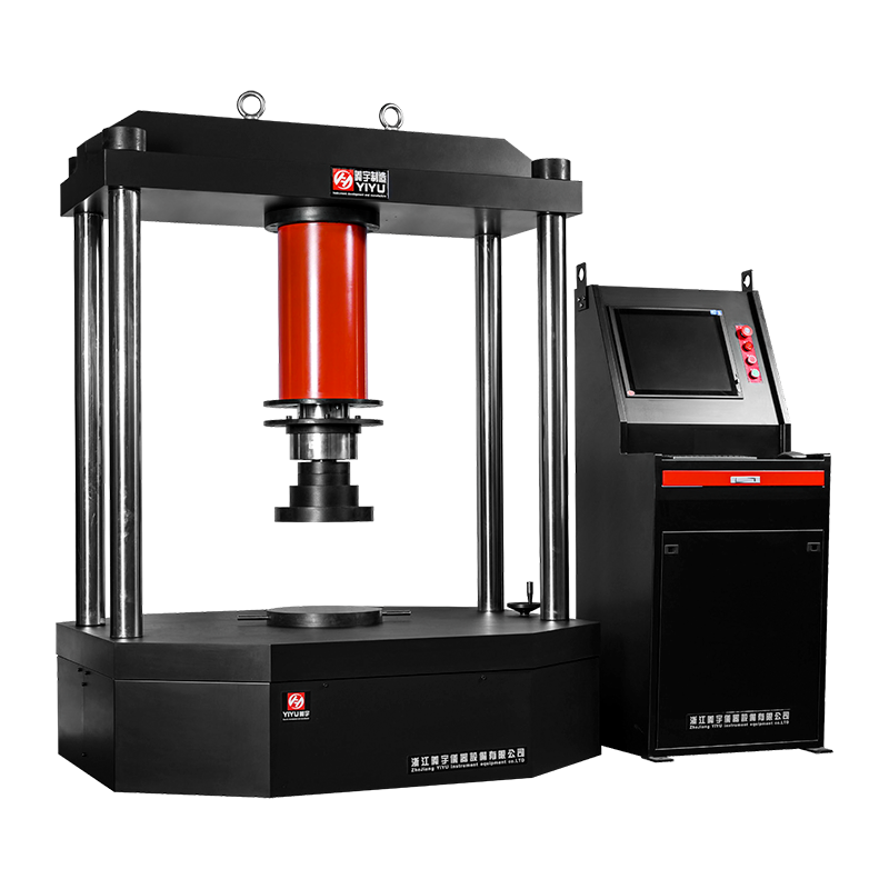
Both formulas produce similar values for typical subgrade soils, and the choice usually follows the standard referenced in the project specification. One point is worth emphasising: the DCP provides an in-situ field CBR estimate, not the laboratory CBR obtained from a soaked mould sample. Laboratory CBR testing uses a rigid loading frame to push a plunger into a compacted specimen at a controlled rate. Many quality-control programmes still require this laboratory result for mix design and compaction acceptance. If you work primarily with compression-type laboratory equipment, our guide on how to use a compression testing machine offers a useful overview of the operating principles.
Worked Example: From DCP Readings to CBR
Let us apply the method to a realistic field dataset. The table below shows readings taken on a low-strength subgrade after the initial seating blows were completed. The seating reading after blow 3 was 42 mm.
Starting from this seating point, seven blows were recorded:
Table 1 – DCP field data for a low-strength subgrade (illustrative readings)
| Blow Number |
Scale Reading (mm) |
Increment (mm) |
Cumulative Penetration (mm) |
| 4 |
61 |
19 |
19 |
| 5 |
83 |
22 |
41 |
| 6 |
108 |
25 |
66 |
| 7 |
136 |
28 |
94 |
| 8 |
167 |
31 |
125 |
| 9 |
201 |
34 |
159 |
| 10 |
238 |
37 |
196 |
The cumulative penetration after seating is 196 mm over 7 blows, so DPI = 196 ÷ 7 = 28 mm/blow. Applying the ASTM formula:
CBR = 292 ÷ 281.12 ≈ 7.0%
This value falls within the typical range for a weak subgrade, which is exactly the situation where DCP testing is most useful for identifying soft spots before paving begins.
Field Considerations and Common Pitfalls
Even with correct arithmetic, a CBR estimate is only as reliable as the field conditions behind it. Keep these points in mind during interpretation:
- Moisture strongly affects both DCP and CBR values. Record the moisture condition at the time of testing, and avoid comparing results taken under significantly different moisture states.
- If the penetration rate changes sharply with depth, do not average the whole profile. Divide the log into distinct layers and calculate a separate DPI for each layer.
- Always observe the seating blows. Neglecting them can overestimate penetration and underestimate the CBR of a well-compacted surface.
- The standard correlation is intended for fine-grained and granular subgrade soils. It becomes unreliable for very soft clays, gravelly materials with large particles, or cemented layers.
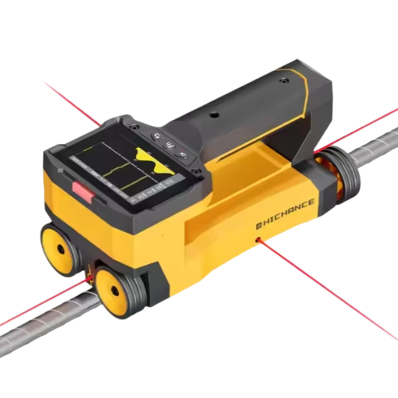
When the DCP result is close to an acceptance threshold, or when the subgrade profile is highly variable, an independent check is wise. A static load test performed directly on the layer provides a more direct measure of bearing capacity and helps confirm the DCP-based CBR estimate. Portable static load testers are commonly used on road subgrades and foundation layers for exactly this purpose.
 HC-ZH20 Static Load Tester for Bearing Capacity VerificationThis portable static load tester offers a direct bearing capacity check, ideal for confirming DCP-based CBR estimates on subgrades and pavement layers.View Product →
Final Recommendations
Calculating CBR from DCP data is not difficult when you follow a consistent routine. Seat the cone, count blows over a measured penetration, compute DPI in millimetres per blow, apply the ASTM correlation, and always note the moisture condition at the time of testing. The DCP will never replace a properly performed laboratory CBR or a static load test, but for rapid site assessment, compaction control, and pavement layer evaluation, it remains an excellent first tool.
If you are responsible for selecting field testing equipment or refining your site procedures, practical questions often come up. You may find the answer in our FAQ section, or reach out to our team directly with your specific testing challenge.

 简体中文
 English
 русский