To use a compression testing machine correctly, place a properly prepared sample centrally between the platens, set the appropriate load rate for your material standard, apply the load smoothly until failure or the target force is reached, then record the peak load and calculate compressive strength. Done right, the process is straightforward — but errors in sample preparation, loading rate, or platen alignment are responsible for the majority of inaccurate test results. This guide walks through every stage in detail, covering concrete, foam, metal, and other common test materials.
What a Compression Testing Machine Actually Does
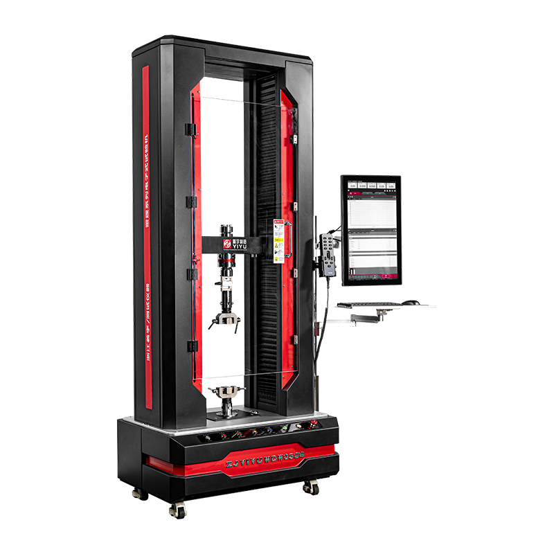
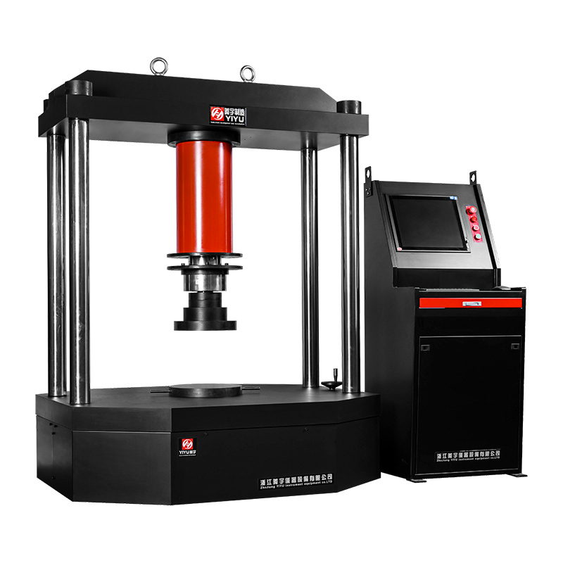
A compression testing machine applies a controlled, measurable compressive force to a specimen and records how the material responds — typically measuring peak load, deformation, and the point of failure. The machine consists of a rigid frame, two opposing platens (one fixed, one moving), a hydraulic or electromechanical load-application system, and a load cell that measures force with high precision.
Modern compression testing machines display results digitally and can output stress-strain curves, peak load values, and compressive strength calculations automatically. Capacities range widely — from 1 kN benchtop units for soft materials like foam and rubber, up to 5,000 kN (5 MN) floor-standing machines used in concrete and structural steel testing. Selecting the right machine capacity for your specimen is the first critical decision.
Types of Compression Testing Machines and Their Applications
Understanding which type of compression testing machine you are working with affects how you operate it and interpret results.
| Machine Type |
Drive System |
Typical Capacity |
Common Applications |
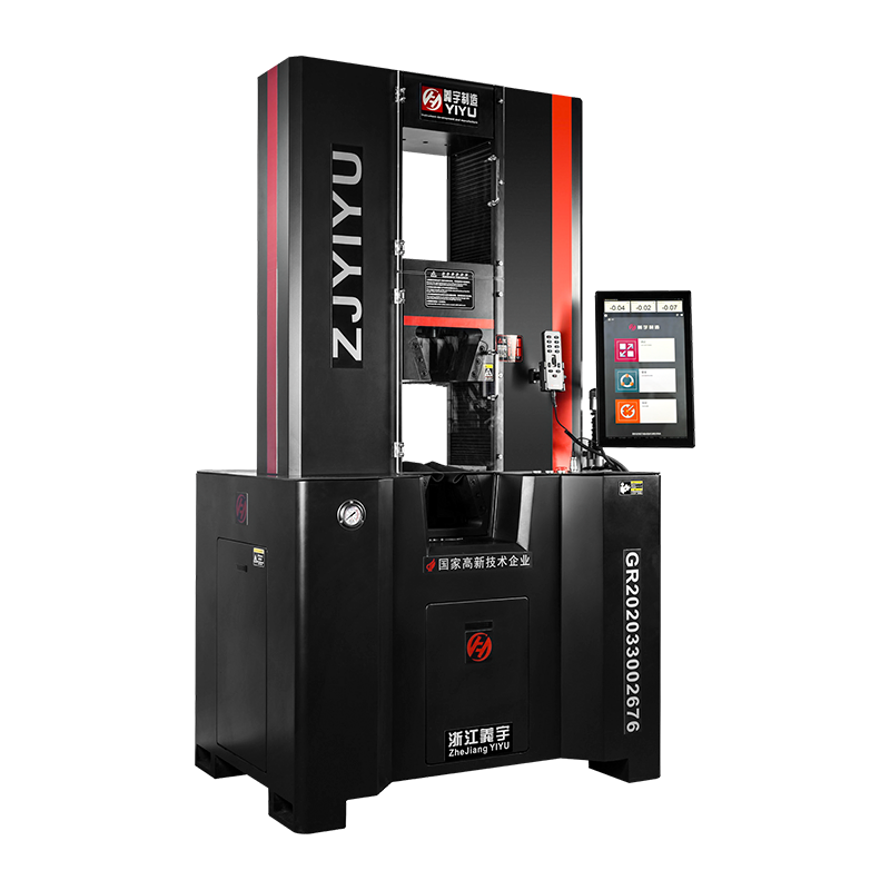
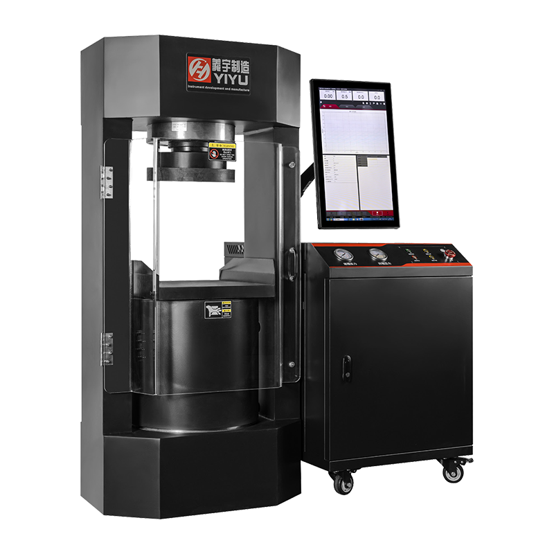
| Hydraulic compression tester |
Hydraulic cylinder |
200 kN – 5,000 kN |
Concrete cubes/cylinders, masonry, rock |
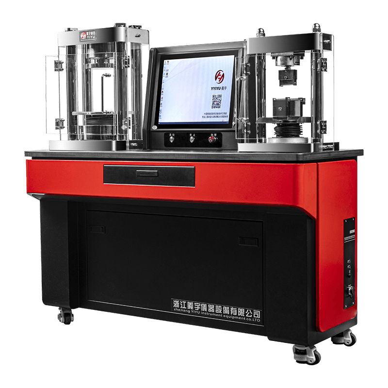
| Electromechanical UTM (compression mode) |
Servo motor + ballscrew |
1 kN – 600 kN |
Plastics, foam, metals, composites |
| Servo-hydraulic dynamic tester |
Servo-controlled hydraulics |
Up to 2,500 kN |
Fatigue and cyclic compression testing |
| Spring-loaded / manual compression tester |
Manual or lever |
Up to 50 kN |
Packaging, tablets, soft materials |
Table 1: Main types of compression testing machines, drive systems, and typical use cases
Essential Pre-Test Checks Before Operating the Machine
Skipping pre-test checks is the fastest route to invalid results or equipment damage. Complete the following before every test session:
- Verify machine calibration is current. Most standards (ASTM, EN, ISO) require compression testing machines to be calibrated at least annually, or after any major service. Check the calibration certificate date and ensure the machine is within its valid calibration period.
- Inspect the platens. Look for surface damage, scoring, or debris. Even small particles between the platen and specimen cause stress concentrations that distort results. Clean platens with a dry cloth before each test.
- Check platen flatness and parallelism. Platens should be within 0.05 mm flatness tolerance for most concrete and structural testing standards. A worn or warped platen introduces eccentric loading.
- Zero the load cell. With no specimen installed and no load applied, confirm the display reads zero. A non-zero baseline reading indicates a tare error that will offset all results.
- Confirm the machine capacity is appropriate. The expected failure load of your specimen should fall between 20% and 80% of the machine's rated capacity for best accuracy. Testing a 10 kN specimen on a 5,000 kN machine produces unreliable low-range readings.
- Check hydraulic fluid level (on hydraulic machines) and inspect for leaks around hose connections and cylinder seals.
Sample Preparation: The Step That Determines Result Quality
Poor sample preparation is responsible for more compression test failures and anomalous results than any machine fault. Each material type has specific preparation requirements defined by its governing test standard.
Concrete Cubes and Cylinders
Concrete specimens must have bearing faces that are flat to within 0.05 mm and perpendicular to the longitudinal axis within 0.5°. Out-of-plane bearing surfaces are the most common cause of premature or asymmetric failure in concrete compression tests. Options for achieving flat faces include:
- Capping with sulphur compound — the traditional method, effective for standard-strength concrete up to approximately 80 MPa.
- Grinding the ends — required for high-strength concrete above 80 MPa and for cylinders where capping compounds may be too weak.
- Neoprene pad systems — an accepted alternative under ASTM C1231, allowing uncapped cylinders when pad hardness and thickness are within specified limits.
Metal Specimens
Metal compression specimens (typically short cylinders with a height-to-diameter ratio of 1.5:1 to 3:1 per ASTM E9) must be machined to tight dimensional tolerances. Surface finish should be Ra ≤ 1.6 µm on bearing faces to prevent friction effects that falsely elevate measured compressive strength.
Foam, Rubber, and Soft Materials
Soft material specimens should be cut to uniform thickness with parallel faces — typically using a sharp die cutter or bandsaw. Specimens must be conditioned at 23°C ± 2°C and 50% ± 5% relative humidity for at least 40 hours before testing, per ISO 1798 and similar standards, as temperature and moisture significantly affect foam and elastomer stiffness.
Step-by-Step Operating Procedure for a Compression Testing Machine
Follow this procedure for a standard compression test. Steps may vary slightly depending on machine type and the test standard being applied — always cross-reference the relevant standard (e.g., EN 12390-3 for concrete, ASTM E9 for metals, ISO 844 for rigid foam).
- Power on the machine and allow warm-up time. Hydraulic machines typically require 5–10 minutes of idle running to stabilize oil temperature. Electromechanical machines are generally ready immediately but benefit from a brief electronics warm-up per the manufacturer's recommendation.
- Enter test parameters into the control software. Input specimen dimensions (cross-sectional area is used to calculate compressive strength from raw load data), test standard, loading rate, and any stop conditions (e.g., stop at 40% load drop after peak).
- Position the specimen centrally on the lower platen. Use the engraved centre marks on the platen surface as alignment guides. Misalignment of more than 1% of the specimen diameter can reduce apparent compressive strength by 5–15% due to eccentric loading.
- Lower the upper platen to make light contact with the specimen. On hydraulic machines, use the rapid approach function to bring the platen close, then switch to fine control for the final few millimetres. Apply a seating load of approximately 1–2% of the anticipated peak load to ensure full, even contact before starting the timed loading phase.
- Start the test at the specified loading rate. For concrete per EN 12390-3, the standard loading rate is 0.6 ± 0.2 MPa/s. For metals per ASTM E9, a strain rate of 0.005 mm/mm per minute is typical in the elastic range. Incorrect loading rates are a common source of non-conforming test reports.
- Do not interrupt the loading once the test has started. Pausing or adjusting the rate mid-test invalidates the result for most standards. Stand clear of the specimen — fragile materials like concrete and ceramics can eject fragments at failure.
- Allow the machine to record the peak load automatically. Modern compression testing machines hold the maximum load reading even after specimen failure. The machine will stop automatically if a load-drop stop condition was programmed.
- Retract the upper platen and remove the specimen. Inspect and describe the failure mode — for concrete, EN 12390-3 defines six standard failure patterns (Types A through F) that indicate whether the result is valid or influenced by specimen defects.
- Record and calculate results. Compressive strength (fc) = Peak Load (F) ÷ Cross-sectional Area (A). Most software calculates this automatically; verify the area input is correct before accepting the result.
- Clean the platens and reset the machine. Remove all debris immediately — fine concrete or ceramic particles left on platens will damage the surface finish and affect subsequent tests.
Loading Rates by Material and Standard
Applying the correct loading rate is one of the most important — and most commonly violated — requirements in compression testing. Rate affects measured strength: loading too fast artificially inflates results; loading too slowly can allow stress relaxation in some materials. The table below summarizes standard loading rates for common materials:
| Material |
Applicable Standard |
Specified Loading Rate |
Rate Type |
| Concrete (cube/cylinder) |
EN 12390-3 |
0.6 ± 0.2 MPa/s |
Stress rate |
| Concrete (cylinder) |
ASTM C39 |
0.14–0.34 MPa/s |
Stress rate |
| Metals |
ASTM E9 |
0.005 mm/mm/min (elastic range) |
Strain rate |
| Rigid cellular plastics (foam) |
ISO 844 |
10% specimen thickness/min |
Displacement rate |
| Plastics (general) |
ISO 604 |
1 mm/min |
Displacement rate |
| Pharmaceutical tablets |
Ph. Eur. 2.9.8 |
Typically 1 mm/min |
Displacement rate |
Table 2: Specified loading rates for compression testing by material type and test standard
Reading and Interpreting Compression Test Results
The primary output of a compression test is the compressive strength, calculated as peak load divided by the original cross-sectional area of the specimen. However, the full load-displacement or stress-strain curve provides much richer information about material behaviour.
Key Values to Extract from the Test Curve
- Peak (ultimate) compressive strength: the maximum stress the specimen sustained before failure. This is the primary reported value in most structural material tests.
- Compressive modulus (Young's modulus in compression): the slope of the linear elastic region of the stress-strain curve. Relevant for metals, stiff plastics, and composites.
- Compressive yield strength: the stress at which permanent plastic deformation begins — identified by a 0.2% offset method for metals or a distinct yield point in the curve.
- Energy absorption (area under the curve): important for packaging foams and crash-protection materials, where the ability to absorb energy matters more than peak strength alone.
Recognising Invalid Test Results
Not every test result is valid for reporting. Discard and retest when:
- The load-displacement curve shows an early non-linear region before the expected elastic range — indicating seating problems or specimen surface irregularities.
- The failure mode for a concrete specimen corresponds to Type E or F per EN 12390-3 — these columnar or corner-break patterns indicate capping failure or poor specimen geometry rather than true material failure.
- The result is more than 15% below the mean of companion specimens tested from the same batch — a strong indicator of an individual defective specimen rather than a genuine low-strength result.
Common Errors When Using Compression Testing Machines
Even experienced operators make repeatable mistakes that compromise test validity. The following are the most frequent errors encountered in laboratory and site testing environments:
- Incorrect specimen centring: even a 5 mm offset on a 150 mm concrete cube introduces measurable eccentricity. Always use platen centre marks and a ruler or template for positioning.
- Using the wrong load range: testing at less than 20% of machine capacity degrades load cell accuracy. Always match specimen expected load to machine range.
- Failing to zero before testing: a load cell left under the weight of a heavy upper platen assembly will read a false preload — all subsequent results will be offset by that amount.
- Applying load too fast manually: on older hydraulic machines with manual valve control, operators often exceed the specified loading rate during the initial phase, falsely elevating peak load readings by 5–10%.
- Testing specimens outside the specified age or conditioning window: concrete specimens tested outside the 28-day ± 3-hour window per EN 12390-3, or foam specimens not conditioned for the required 40 hours, produce non-comparable results.
- Not inspecting the spherical seating device: the upper platen on most compression testing machines is mounted on a spherical seat that allows self-levelling. If this seat is seized or dirty, it cannot compensate for non-parallel specimen faces, resulting in eccentric loading.
Safety Precautions When Operating Compression Testing Machines
Compression testing releases large amounts of stored elastic energy at failure, particularly in brittle materials like concrete, ceramics, and rock. Safety is non-negotiable.
- Always use the machine's fragment guards or safety shields when testing brittle materials. A 150 mm concrete cube failing at 1,000 kN can eject fragments at high velocity.
- Wear safety glasses and steel-toe footwear as a minimum during all compression tests on hard materials.
- Never reach into the machine while the platens are in motion or under load. Use the emergency stop if the machine behaves unexpectedly.
- On hydraulic machines, never exceed the rated system pressure. Overpressure can cause hose failure and hydraulic fluid ejection — a serious burn and fire hazard.
- Ensure all bystanders are at a safe distance — a minimum of 1.5 metres from the machine during the active loading phase is a reasonable guideline for machines above 200 kN.
Routine Maintenance to Keep Compression Testing Machines Accurate
A well-maintained compression testing machine retains its measurement accuracy and mechanical reliability for decades. Neglect accelerates platen wear, introduces calibration drift, and risks hydraulic system failures.
| Maintenance Task |
Frequency |
Purpose |
| Clean platens |
After every test |
Prevent surface damage and contamination |
| Lubricate spherical seat and guide columns |
Monthly or per manufacturer schedule |
Ensure smooth, eccentric-free platen movement |
| Check hydraulic fluid level and condition |
Monthly |
Maintain system pressure accuracy |
| Verify load cell zero and span |
Before each test session |
Confirm measurement baseline accuracy |
| Full calibration by accredited body |
Annually (or per standard requirement) |
Maintain traceability to national standards |
| Inspect and replace platen surfaces |
When flatness exceeds 0.05 mm tolerance |
Prevent eccentric loading from worn surfaces |
Table 3: Recommended maintenance schedule for compression testing machines
 简体中文
简体中文
 English
 русский