A universal testing machine (UTM) measures the mechanical properties of materials — including tensile strength, compressive strength, flexural strength, and elongation — by applying controlled forces and recording the material's response. To use one correctly, you must select the right machine type (electronic or hydraulic), install the appropriate grips or fixtures, set test parameters in the software, zero the load and extension, then run the test while monitoring the load-displacement curve in real time. This guide covers every step for both electronic and hydraulic UTMs, with practical data and comparisons to help you get accurate, repeatable results.
Electronic vs. Hydraulic Universal Testing Machines: Which Do You Need?
Choosing the correct machine type is the first and most consequential decision. Using the wrong platform can produce inaccurate data or even damage specimens and equipment.
Table 1: Key differences between electronic and hydraulic UTMs
| Feature |
Electronic UTM |
Hydraulic UTM |
| Typical force range |
0.5 N – 600 kN |
50 kN – 3,000 kN+ |
| Speed control |
Precise (servo motor, ±0.5%) |
Good (servo valve, ±1–2%) |
| Best for |
Polymers, composites, thin metals, medical devices |
Steel, concrete, heavy structural components |
| Noise & maintenance |
Low noise, minimal upkeep |
Louder, requires fluid checks |
| Displacement resolution |
Up to 0.001 mm |
Typically 0.01 mm |
| Energy consumption |
Lower |
Higher (hydraulic pump running continuously) |
As a practical rule: if your specimen requires more than 600 kN of force, choose a hydraulic UTM. For precision low-force work — such as testing a 0.2 mm polymer film or a biomedical suture — an electronic UTM with a 10 N load cell will yield far more meaningful data.
Essential Components You Must Understand Before Operating
Regardless of machine type, every UTM shares the same core components. Misidentifying or misusing any one of them is a leading cause of invalid test results.
Load Frame
The structural backbone that holds all forces during the test. Frames are rated by their maximum load capacity. Never exceed 80% of the rated frame capacity in routine testing to avoid fatigue damage to the frame over time.
Load Cell
The force transducer that converts mechanical force into an electrical signal. Load cells have their own capacity ratings — for example, a 1 kN load cell installed on a 100 kN frame means the machine is effectively limited to 1 kN for that configuration. Always match the load cell to within 20–100% of the expected peak force of your specimen. Using a 100 kN load cell to test a specimen that breaks at 50 N will give unreliable readings.
Crosshead and Actuator
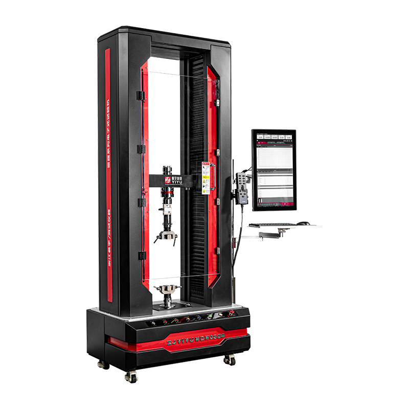
In electronic UTMs, the crosshead is driven by a precision ball screw or lead screw powered by a servo motor. In hydraulic UTMs, the actuator (hydraulic ram) applies force via pressurized fluid. The crosshead moves at a programmed speed — typically expressed in mm/min — which controls the strain rate on the specimen.
Grips and Fixtures
Grips are the interface between the machine and the specimen. Common types include:
- Wedge-action grips — self-tightening under load, ideal for flat or round metal specimens
- Pneumatic grips — consistent clamping force, suited for thin films and rubber
- Compression platens — flat plates for compressive tests on foams, concrete cylinders, or tablets
- Three-point and four-point bend fixtures — for flexural testing of beams and bars
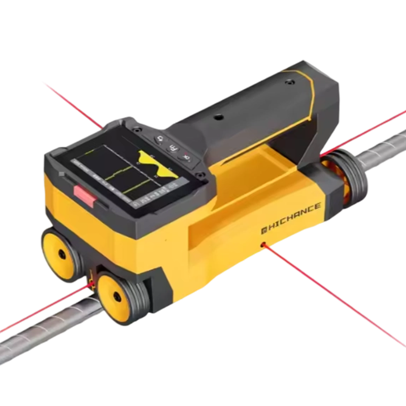
Extensometer
A clip-on or non-contact (video or laser) device that measures actual specimen strain independently of crosshead displacement. For accurate Young's modulus calculation, an extensometer is mandatory — crosshead displacement includes machine compliance and grip slip, introducing errors of 10–30% in stiffness measurements.
Step-by-Step: How to Use an Electronic Universal Testing Machine
Electronic UTMs are the most widely used platform in quality control and research labs. The following procedure covers a standard tensile test, the most common test type, in compliance with standards such as ASTM E8, ISO 6892-1, or ASTM D638.
- Power on the machine and launch the control software. Allow a minimum 15-minute warm-up period so the servo drive and load cell electronics reach thermal equilibrium, reducing drift.
- Select and install the correct load cell. Confirm the rated capacity on the load cell label. Torque the mounting fasteners to the manufacturer's specification — under-torquing causes signal noise; over-torquing can damage the transducer.
- Install the appropriate grips. For a dog-bone tensile specimen per ASTM D638, install wedge-action flat grips. Confirm grip faces are clean and free of debris that could cause uneven clamping.
- Enter specimen dimensions in the software. Measure gauge length, width, and thickness using calibrated calipers. For round specimens, measure diameter at three points and use the average. The software uses these values to calculate engineering stress (Force ÷ Original cross-sectional area).
- Select or create a test method. Define: test type (tension, compression, flexure), crosshead speed (e.g., 5 mm/min for metals per ISO 6892-1 Method A, or 50 mm/min for plastics per ASTM D638), load and extension limits, and data acquisition rate (typically 10–100 Hz).
- Zero the load and extension. With grips installed but no specimen loaded, zero both the force and displacement channels. This eliminates the weight of the grips from the force reading.
- Load the specimen. Insert the specimen into the lower grip first, then the upper grip. Apply only enough clamping force to hold the specimen — excessive pre-stress will affect the yield point measurement.
- Attach the extensometer (if measuring modulus or yield strain). Position the knife edges exactly at the marked gauge length. For a 50 mm gauge length extensometer, verify the gauge marks on the specimen are exactly 50 mm apart.
- Start the test. Monitor the live load-displacement curve. For most tensile tests, the curve should show a linear elastic region, a yield point (or proportional limit), plastic deformation, and fracture.
- Remove the specimen after fracture and save the test report. The software will automatically calculate UTS, yield strength, elongation at break, and Young's modulus from the recorded data.
A typical electronic UTM tensile test on a steel coupon at 5 mm/min takes approximately 3–8 minutes from specimen loading to fracture, depending on ductility.
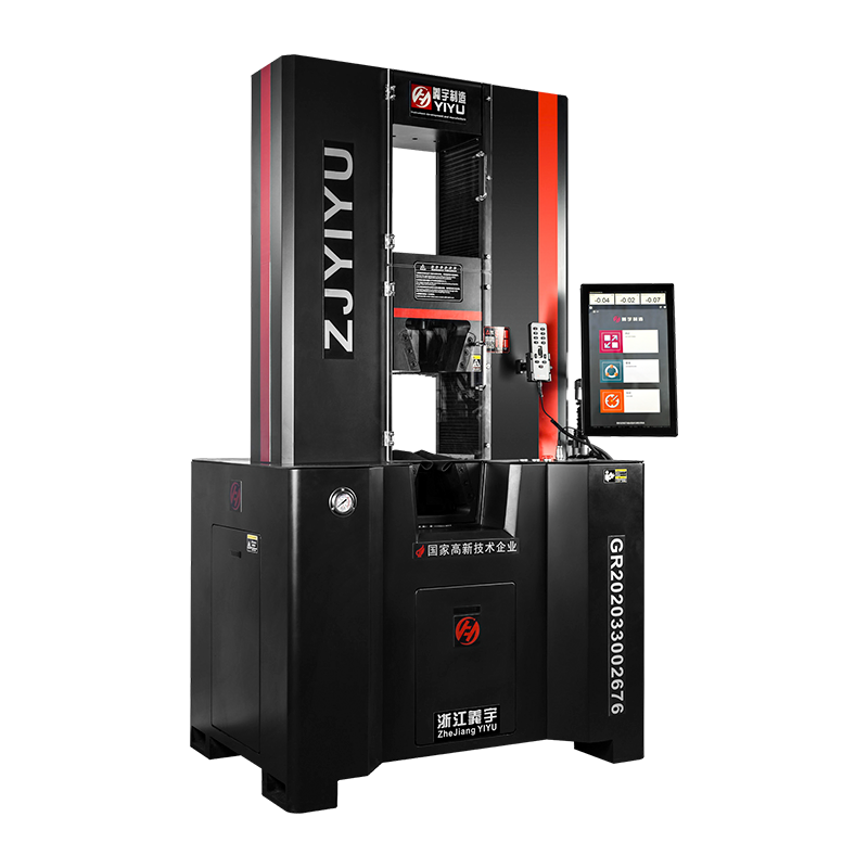
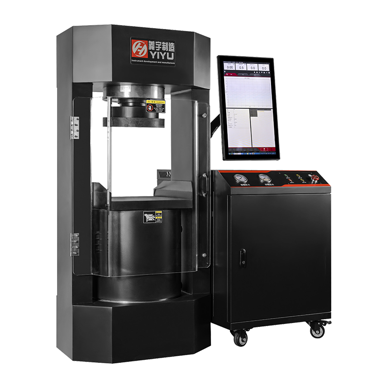
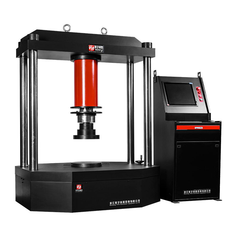
Step-by-Step: How to Use a Hydraulic Universal Testing Machine
Hydraulic UTMs are the standard platform for heavy structural testing. The procedure below covers high-force tensile or compressive testing of steel or concrete specimens.
- Check hydraulic fluid level and condition. Low fluid causes pressure drops mid-test; contaminated fluid degrades servo valve performance. Use only the fluid grade specified in the manual (commonly ISO VG 46 hydraulic oil).
- Start the hydraulic power unit (HPU). Allow the pump to run for 5–10 minutes to circulate fluid and reach operating temperature (typically 40–50°C). Most machines display fluid temperature on the control panel.
- Select test configuration. For a compressive test on a 150 mm concrete cylinder per ASTM C39, install compression platens. For a reinforcing bar tensile test per ASTM A615, install hydraulic wedge grips rated for the bar diameter.
- Configure the servo controller. Set load control or displacement control mode. For quasi-static material tests, displacement control at a defined rate (e.g., 0.25 MPa/s stress rate for concrete compression per ASTM C39) is standard. For structural component tests, load control is common.
- Zero the load cell and position transducer (LVDT). With no specimen under load, set both channels to zero through the control software or front panel.
- Position and secure the specimen. For compressive tests, center the specimen under the upper platen within ±1 mm to avoid eccentric loading, which artificially reduces measured strength by up to 15%.
- Apply a small pre-load (contact load). Hydraulic machines benefit from a small pre-load (typically 1–5% of expected maximum) to seat the specimen and eliminate slack in fixtures before starting the controlled ramp.
- Run the test. The servo valve modulates hydraulic flow to maintain the programmed load or displacement rate. Monitor system pressure — if pressure approaches the relief valve setting, stop the test immediately.
- After specimen failure, reduce pressure slowly before opening grips or removing platens. Sudden pressure release can cause fixture ejection in high-force setups.
- Shut down the HPU after completing all tests. Leaving the pump running unnecessarily degrades fluid and seals.
Setting Test Parameters Correctly: The Details That Determine Data Quality
Incorrect test parameters are responsible for a significant portion of non-reproducible UTM results. Pay close attention to the following settings:
Crosshead Speed and Strain Rate
Many users input a crosshead speed in mm/min without considering how it translates to strain rate. Strain rate (s⁻¹) = crosshead speed ÷ gauge length. For a 50 mm gauge length specimen tested at 5 mm/min, the strain rate is 0.1 min⁻¹ (0.00167 s⁻¹). Exceeding the standard strain rate by 10× can increase the measured yield strength of mild steel by 5–15%, producing non-comparable data.
Test Stop Conditions
Always define at least two stop conditions in the software:
- Load drop (% of peak load) — typically set at 20–40% load drop from peak to detect fracture automatically
- Maximum extension limit — prevents the crosshead from traveling beyond the grip separation range, which would damage the machine
Data Acquisition Rate
For slow quasi-static tests (plastics, composites at 50 mm/min), 10 Hz is sufficient. For fast fracture tests or impact-adjacent tests, increase to 100–1,000 Hz. A rate too low will miss the exact yield point or maximum load, leading to underreported UTS values.
Preload
A small preload (0.5–2% of expected failure load) removes initial slack and confirms the specimen is properly seated. However, do not zero the extensometer after applying preload unless the test standard explicitly requires it, as this artificially offsets the strain baseline.
Common Test Types and Their Standard Procedures
Universal testing machines are not limited to tensile testing. The following table summarizes the most common test types, the relevant standards, and key setup notes.
Table 2: Common UTM test types and associated standards
| Test Type |
Common Standards |
Typical Speed |
Key Fixture |
| Tensile (metals) |
ASTM E8, ISO 6892-1 |
2–10 mm/min |
Wedge grips |
| Tensile (plastics) |
ASTM D638, ISO 527 |
5–500 mm/min |
Flat wedge or pneumatic grips |
| Compression |
ASTM C39, ISO 604 |
1–5 mm/min |
Compression platens |
| Flexure / Bend |
ASTM D790, ISO 178 |
2–10 mm/min |
3-point or 4-point bend fixture |
| Peel / Adhesion |
ASTM D903, ISO 8510 |
100–300 mm/min |
Peel fixture, 90° or 180° |
| Shear |
ASTM D732, ISO 14130 |
1–10 mm/min |
Shear fixture or lap-joint grips |
Safety Practices That Cannot Be Skipped
Universal testing machines generate enormous forces in a compact space. A 100 kN tensile specimen fracture releases energy equivalent to a significant mechanical impact. Strict safety protocols protect operators and equipment.
- Always wear safety glasses and, for high-force hydraulic tests, a face shield. Specimen fragments and grip components have caused serious injuries during high-energy fractures.
- Install safety shields or guards around the test zone, especially for brittle materials (ceramics, glass, cast iron) that shatter without warning.
- Never stand in line with the loading axis during a test. Position yourself to the side of the machine.
- Set hardware limit switches at both ends of crosshead travel. These provide a physical stop independent of software, preventing the crosshead from over-traveling and damaging the load cell or frame.
- For hydraulic UTMs, never exceed the system's rated working pressure (commonly 210–280 bar). Overpressure can rupture hydraulic lines or seals.
- Inspect grips and fixtures for cracks or wear before each session. A grip failure under load is one of the most dangerous failure modes in a UTM laboratory.
Calibration and Verification: Keeping Results Traceable
Uncalibrated UTMs produce data that cannot be used in engineering decisions or reported to customers. Most quality systems require annual calibration at a minimum.
Force Calibration
Performed using a certified deadweight machine or a reference load cell (class 0.5 per ISO 7500-1). The UTM must read within ±1% of the applied reference force at each calibration point across the full range of the load cell. Calibration should cover at least 5 points from 20% to 100% of load cell capacity.
Crosshead Displacement Verification
Use a calibrated LVDT or dial gauge to verify that the crosshead travels the commanded distance. For electronic UTMs, accuracy is typically within ±0.5% of reading; hydraulic UTMs are typically within ±1%.
Extensometer Calibration
Extensometers must be calibrated to ISO 9513 Class 1 or ASTM E83 Class B1 for modulus measurements. This involves displacing the extensometer a known amount using a micrometer stage and comparing the output. Recalibrate after any drop or physical impact.
Keep all calibration certificates with traceability to national standards (NIST, NPL, PTB, etc.) on file and accessible during audits. In regulated industries such as aerospace (AS9100) or automotive (IATF 16949), using an out-of-calibration UTM invalidates all test data generated since the last valid calibration.
Troubleshooting the Most Frequent Problems
Even experienced operators encounter recurring issues. Here are the most common problems and their root causes:
Specimen Slipping in Grips
Visible as a sudden load drop without specimen fracture, or a saw-tooth load curve. Causes: worn grip faces, incorrect grip type for specimen geometry, specimen surface contamination (oils, moisture), or insufficient clamping pressure. Solution: replace grip inserts, clean specimen ends, or switch to serrated faces for smooth specimens.
Non-Linear Initial Response (Toe Region)
A curved initial portion of the stress-strain curve before the linear elastic region indicates specimen misalignment, slack in the load train, or specimen end tabs not parallel. Per ASTM E111, the toe region must be corrected by offsetting the strain axis to the intersection of the linear elastic slope and the strain axis. This is done in post-processing in the software.
Erratic Load Readings (Electronic UTM)
Typically caused by damaged load cell cables, poor electrical grounding, vibration from nearby equipment, or electromagnetic interference. Check cable connectors first — this resolves over 60% of signal noise issues. Ensure the frame is properly grounded to building earth.
Unstable Load Control (Hydraulic UTM)
Oscillating load in load-control mode indicates servo valve contamination, air in the hydraulic lines, or incorrect PID tuning for the specimen stiffness. Bleed the hydraulic circuit to remove air. If oscillation persists, the servo valve may require cleaning or replacement — a service task for qualified technicians.
Routine Maintenance Schedule for Long-Term Reliability
Preventive maintenance directly determines the usable lifespan of a UTM — well-maintained machines regularly operate for 20+ years. Follow the schedule below:
Table 3: Recommended UTM maintenance intervals
| Frequency |
Electronic UTM Tasks |
Hydraulic UTM Tasks |
| Daily |
Clean grip faces, inspect cables |
Check fluid level, inspect for leaks |
| Monthly |
Lubricate ball screws, check drive belt tension |
Sample fluid for particle count, inspect hoses |
| Quarterly |
Verify software calibration constants, inspect load cell connector |
Replace hydraulic filter element, check pump pressure output |
| Annually |
Full force and displacement calibration, replace encoder battery backup |
Full force calibration, replace hydraulic fluid, inspect servo valve |
For hydraulic UTMs, fluid cleanliness is the single most important maintenance factor. Contaminated fluid is responsible for over 70% of servo valve failures, which are among the most expensive hydraulic UTM repairs, often costing $3,000–$15,000 per valve replacement.
 简体中文
简体中文
 English
 русский