The Power and Precision of Hydraulic UTMs
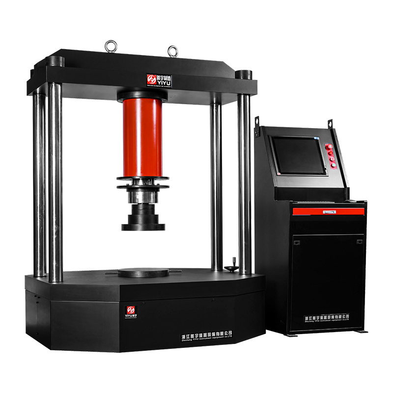
A Hydraulic Universal Testing Machine (UTM) is the industry standard for high-capacity material testing, specifically engineered to apply massive tensile, compressive, or transverse loads ranging from 300kN to 3000kN (and beyond). Unlike electromechanical systems that use lead screws, hydraulic UTMs utilize high-pressure fluid dynamics to deliver the force necessary to fracture high-strength alloys, reinforced concrete, and large-scale structural components. For quality control managers and civil engineers, the definitive advantage of the hydraulic system is its exceptional stiffness and durability under continuous high-load cycles, providing a more stable testing platform for heavy-duty industrial materials where standard motorized machines would reach their mechanical torque limits.
Mechanical Principles and Structural Configuration
The architecture of a hydraulic UTM is designed to manage immense reactive forces while maintaining axial alignment. Understanding the interaction between the hydraulic ram and the load frame is essential for accurate data collection.
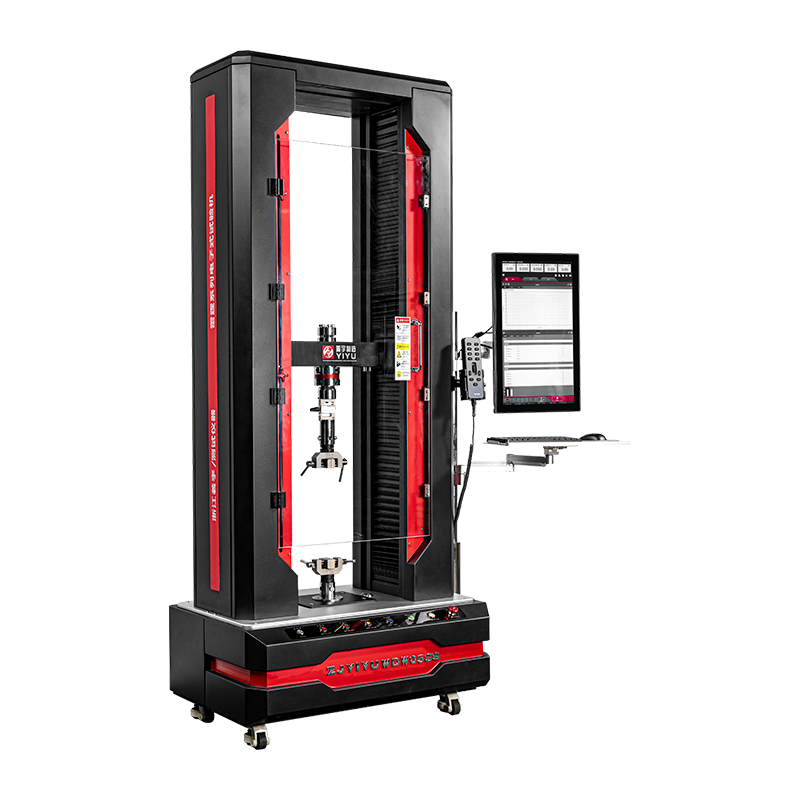
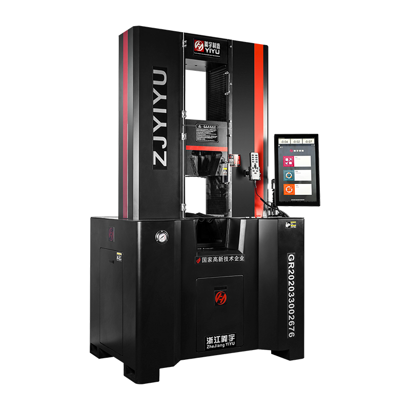
The Dual-Space Load Frame
Most high-capacity hydraulic machines utilize a dual-space design. The upper space is typically reserved for tension testing, while the lower space (between the moving crosshead and the base) is used for compression and bending. This eliminates the need for technicians to constantly swap heavy grips, significantly increasing throughput in high-volume testing labs. The columns are often induction-hardened and chrome-plated to withstand the abrasive dust common in construction material testing.
Servo-Hydraulic Control Systems
In the past, hydraulic machines were manually controlled via needle valves, leading to inconsistent strain rates. Modern Servo-Controlled Hydraulic Systems utilize high-frequency closed-loop feedback. By monitoring a load cell or extensometer at rates exceeding 1,000 Hz, the servo valve can adjust fluid flow instantly to maintain a precise constant strain rate (e.g., 0.005 mm/mm/min), which is mandatory for compliance with standards like ASTM E8 or ISO 6892-1.
Technical Comparison: Hydraulic vs. Electromechanical UTMs
Choosing the right drive system is a constructive decision based on the maximum expected load and the required crosshead travel. The following table highlights why hydraulic systems are preferred for specific heavy-duty applications.
Table 1: Performance Comparison of UTM Drive Technologies
| Parameter |
Hydraulic Drive |
Electromechanical Drive |
| Typical Force Range |
300kN to 5000kN+ |
0.1kN to 600kN |
| Testing Speed Range |
Low to Moderate |
Ultra-low to High |
| Frame Stiffness |
Maximum (Rigid) |
High (Dependent on screws) |
| Maintenance Needs |
Fluid/Seal Management |
Lubrication/Belt Check |
Advanced Gripping and Fixturing Technology
In a hydraulic UTM, the method of holding the specimen is as important as the force application itself. Improper gripping can lead to specimen slippage or "premature breaks" near the jaw face, which invalidates the test data.
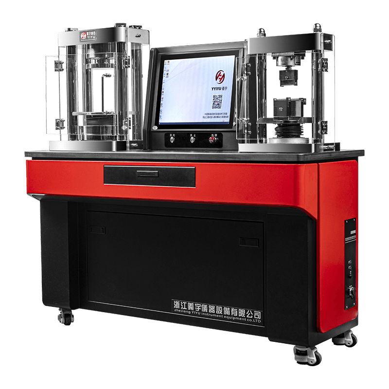
Hydraulic Side-Acting Grips
For high-capacity testing, manual wedge grips are often insufficient. Hydraulic side-acting grips provide a constant clamping force that is independent of the tensile load. This is critical for materials that undergo significant "necking" (thinning) before fracture, such as rebar or structural steel. The clamping pressure can reach over 700 bar, ensuring that even the slickest hardened surfaces remain secured.
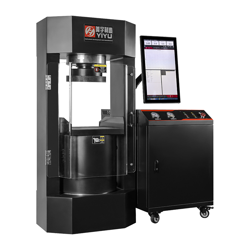
Compression Platens and Flexure Fixtures
When testing concrete cubes or cylinders (compliant with ASTM C39), the platens must be spherically seated to accommodate non-parallel specimen ends. Hydraulic UTMs often feature large-diameter platens (up to 300mm) that are hardened to 55-60 HRC to prevent indentation from high-strength concrete aggregates.
Data Acquisition and Software Integration
The true value of a modern hydraulic UTM lies in its ability to transform raw force and displacement into actionable engineering insights via sophisticated software packages.
- Real-time Curve Plotting: Modern systems plot Stress-Strain, Force-Extension, and Load-Time curves simultaneously. This allows engineers to identify the Upper and Lower Yield Points and the Ultimate Tensile Strength (UTS) instantly.
- Automatic Break Detection: The software monitors for a sudden drop in load (typically 10-50%) to immediately stop the hydraulic ram upon specimen failure, preventing damage to the load cell or the fractured specimen ends.
- Extensometry Integration: For accurate Young's Modulus calculations, software must synchronize data from Clip-on, Long-travel, or Video Extensometers. Modern video extensometers can track strain over 1000mm without physical contact, which is ideal for high-energy hydraulic fractures.
Essential Maintenance for Hydraulic Longevity
A hydraulic UTM is a long-term investment that can last 20 to 30 years with a rigorous maintenance schedule. Because these machines operate under extreme pressure, fluid cleanliness is the most critical variable.
Oil Filtration and Cooling
The hydraulic oil must be kept free of particulates that could clog the sensitive servo-valves. It is recommended to replace 10-micron filters every 2,000 hours of operation. Furthermore, high-use labs should utilize water-cooled or air-cooled heat exchangers to maintain an oil temperature below 50°C, as overheated oil loses viscosity and leads to internal seal leakage.
Annual Calibration Requirements
To maintain legal and quality certification (ISO 9001/ISO 17025), a hydraulic UTM must be calibrated annually using a traceable proving ring or master load cell. The allowable error is typically within ±0.5% or ±1.0% of the indicated load. Regular calibration ensures that the high-pressure transducers have not drifted due to repeated stress-loading.
Conclusion: Strategic Selection Criteria
When investing in a hydraulic universal testing machine, the decision should be guided by a constructive analysis of your facility's long-term material roadmap. If your testing requirements frequently exceed 600kN or involve structural materials like rebar (Grade 60/75), a hydraulic system is the only viable choice. Prioritize machines with closed-loop servo control, modular grip systems, and robust software suites. By focusing on frame stiffness and hydraulic efficiency, you ensure that your laboratory can deliver high-accuracy, repeatable data for the most demanding engineering applications in the world.
 简体中文
简体中文
 English
 русский