Tensile and compression testing machines both measure how materials respond to applied force, but they load specimens in opposite directions and serve fundamentally different engineering purposes. If your application requires measuring a material's resistance to being pulled apart—ultimate tensile strength, elongation, yield point—you need a tensile testing machine. If you need to measure resistance to being crushed or squeezed—compressive strength, deformation under load, elastic modulus in compression—you need a compression testing machine. Many universal testing machines (UTMs) can perform both, but dedicated compression testers remain the preferred choice for concrete, ceramics, and high-load structural materials testing where compressive performance is the sole concern. This article gives you a rigorous, side-by-side breakdown to guide your selection.
Fundamental Principle: How Each Machine Loads the Specimen
The core mechanical difference between the two machine types lies in the direction and nature of the force applied to the test specimen.
Tensile Testing Machines
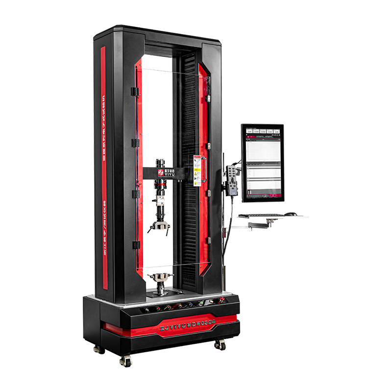
A tensile testing machine grips both ends of a standardised specimen—typically a dog-bone or dumbbell shape—and pulls them apart at a controlled rate. The crosshead moves upward (or outward in horizontal configurations) while the lower grip remains fixed or moves in the opposite direction. As the specimen elongates, the load cell records the force required to sustain each increment of extension until the specimen fractures. Key measurements captured include:
- Ultimate tensile strength (UTS) – the maximum stress the material sustains before fracture
- Yield strength – the stress at which permanent plastic deformation begins
- Elongation at break – a measure of ductility expressed as a percentage increase in gauge length
- Young's modulus – the ratio of stress to strain in the elastic region, indicating material stiffness
Compression Testing Machines
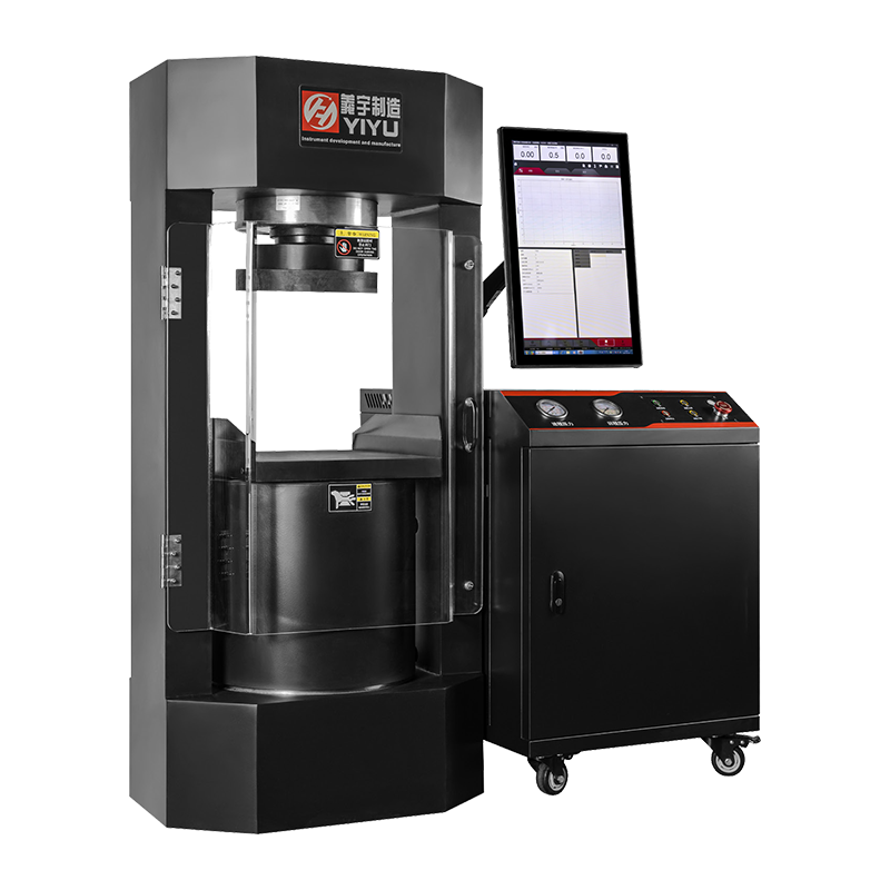
A compression testing machine drives two platens together, squeezing the specimen between them at a controlled rate. The specimen—a concrete cube, cylinder, ceramic disc, foam block, or similar—is placed on the lower fixed platen, and the upper platen descends under hydraulic or electromechanical force. Key measurements include:
- Compressive strength – the maximum compressive stress at failure, expressed in MPa or N/mm²
- Elastic modulus in compression – stiffness characterisation for brittle and semi-brittle materials
- Deformation under sustained load – for materials like foam, rubber, and soft polymers
- Crushing load – for packaging, structural cores, and civil engineering specimens
Machine Architecture and Design Differences
The opposing force directions produce significant differences in how each machine type is structurally designed and what components it requires.
Frame Configuration
Tensile testing machines typically use a two-column or four-column vertical frame where the crosshead travels upward against fixed grips. The frame must handle the full tensile load in bending as well as direct tension, requiring a stiff, well-braced structure. Standard laboratory tensile testers range from 1 kN to 600 kN capacity, with specialist machines reaching 2,000 kN or more for wire rope and structural steel testing.
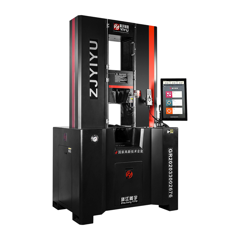
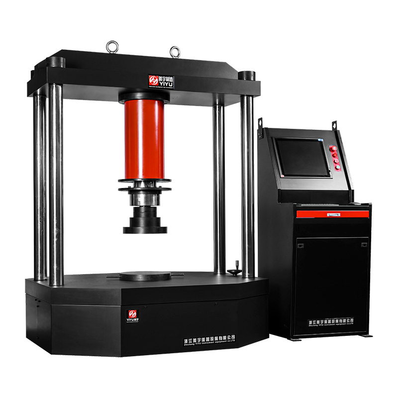
Compression testing machines—particularly those used for concrete and construction materials—are often single-space, low-profile machines with a rigid base and a single moving upper platen. Because compression loads the frame in pure axial compression rather than bending, the structure can be more compact relative to its force capacity. Dedicated concrete compression testers are commonly available in capacities of 1,000 kN to 3,000 kN (1 to 3 MN), with heavy-duty civil engineering machines reaching 10,000 kN.
Grips vs. Platens
Tensile machines require grips that securely hold both ends of the specimen without slipping or causing stress concentrations at the grip faces. Common grip types include wedge-action grips (self-tightening under load), hydraulic grips (for high-force and high-throughput applications), and pneumatic grips (for delicate or flexible specimens). Grip selection significantly affects test result validity—incorrect grips cause premature failure at the grip interface rather than in the specimen gauge length, invalidating the test.
Compression machines use hardened steel platens, typically ground flat to within 0.025 mm and case-hardened to 55 HRC or higher to resist indentation from aggregate in concrete or ceramic specimens. One platen is usually spherically seated—it self-levels to compensate for specimen face non-parallelism of up to ±1 to 2 degrees—ensuring uniform load distribution and preventing eccentric loading that would artificially reduce measured compressive strength.
Drive Systems
Both machine types use either electromechanical (screw-driven) or hydraulic drive systems, but the application emphasis differs:
- Electromechanical drives offer superior displacement control accuracy (typically ±0.1% of set speed) and are preferred for tensile testing of polymers, composites, and textiles where strain rate control and precise elongation measurement are critical
- Hydraulic drives are favoured in high-capacity compression testing where forces above 500 kN are required, offering compact power delivery and smooth load application at very high force levels; dedicated concrete compression testers are almost universally hydraulic above 1,000 kN
Side-by-Side Comparison of Key Specifications
Direct comparison of tensile and compression testing machines across critical specification parameters
| Parameter |
Tensile Testing Machine |
Compression Testing Machine |
| Force Direction |
Axial tension (pulling apart) |
Axial compression (squeezing) |
| Typical Capacity Range |
1 kN – 2,000 kN |
50 kN – 10,000 kN |
| Specimen Holding |
Grips (wedge, hydraulic, pneumatic) |
Hardened platens (spherically seated) |
| Primary Drive |
Electromechanical (screw) |
Hydraulic (high capacity) |
| Frame Height |
Tall (crosshead travel needed) |
Low-profile (short platen travel) |
| Specimen Preparation |
Precision-machined dog-bone shape |
Cube, cylinder, or as-received block |
| Primary Industries |
Metals, plastics, textiles, composites |
Concrete, ceramics, rock, packaging |
| Key Standards |
ISO 6892-1, ASTM E8, ISO 527 |
EN 12390-4, ASTM C39, ISO 4012 |
Compression Testing Machines: Applications and Industry Use Cases
Compression testing machines serve a wider range of material categories than is commonly assumed. While concrete testing dominates the market by volume, dedicated compression testers are essential across multiple industries:
Construction and Civil Engineering
Concrete compressive strength testing is the most widespread use of compression testing machines globally. Standard test specimens are 150 mm cubes (EN 12390-3) or 150 × 300 mm cylinders (ASTM C39). Normal-strength concrete typically achieves compressive strengths of 20 to 40 MPa; high-performance concrete can reach 100 MPa or more. Testing machines for this application must comply with EN 12390-4 (Europe) or ASTM C1231/C39 (North America), specifying requirements for platen flatness, spherical seating, load application rate (typically 0.2 to 1.0 MPa/s), and load cell accuracy (Class 1: ±1% of indicated load).
Ceramics and Refractory Materials
Advanced ceramics used in aerospace, electronics, and medical implants are characterised almost entirely by compressive and flexural strength because ceramic materials are brittle and their tensile strength is typically only 10 to 25% of their compressive strength. Testing these materials requires machines with very stiff frames (high frame rigidity minimises stored elastic energy released catastrophically at fracture), hardened carbide or ceramic platens, and safety shields to contain fragments.
Packaging and Foam Industries
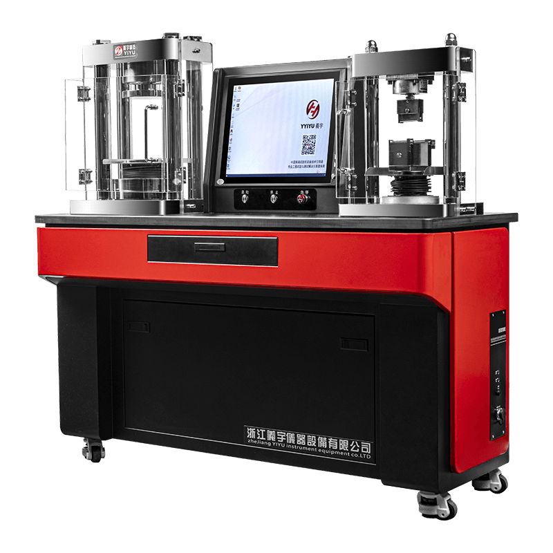
Corrugated board, expanded polystyrene, polyurethane foam, and moulded pulp packaging are tested in compression to verify protective performance. Here, compression testing machines operate at much lower force ranges—typically 1 to 50 kN—with precise displacement control and high-resolution load measurement to capture the characteristic crush curve of foam materials, which shows an initial elastic region, a plateau of progressive cell collapse, and a final densification zone.
Geotechnical and Rock Mechanics
Rock core samples from mining, tunnelling, and petroleum engineering are tested for unconfined compressive strength (UCS) to classify rock mass quality and guide excavation design. Rock specimens typically require machines in the 500 kN to 2,000 kN range, with stiff frames and high data acquisition rates to capture the brittle post-peak behaviour of hard rock.
When a Universal Testing Machine Replaces Both
A universal testing machine (UTM) is designed to perform both tensile and compression tests—and increasingly, flexural, shear, and peel tests—by reconfiguring fixtures within the same machine frame. For laboratories that test a wide range of materials and need both test modes, a UTM often provides better value than purchasing two dedicated machines.
However, UTMs make meaningful compromises in both directions:
- UTMs are rarely available above 600 kN in electromechanical configurations—for concrete testing at 3,000 kN, a dedicated hydraulic compression tester is still required
- Compression platen alignment in a UTM depends on the crosshead alignment system, which is designed primarily for tensile coaxiality; dedicated compression machines with independently mounted spherical seats provide more reliable load uniformity
- High-throughput concrete QC laboratories testing hundreds of specimens per day benefit from the speed and simplicity of a dedicated compression tester over a multi-purpose UTM that requires fixture changes between tests
The decision rule is straightforward: if more than 80% of your testing is one type, invest in a dedicated machine; if your workload is genuinely mixed, a UTM is the more economical and space-efficient solution.
Key Standards Governing Each Machine Type
Compliance with the correct testing standard is not optional—it determines whether your results are legally defensible, inter-laboratory comparable, and suitable for material certification. The most important standards for each machine type are:
Tensile Testing Standards
- ISO 6892-1 – Metallic materials: tensile testing at room temperature; the primary international standard for metals
- ASTM E8/E8M – Standard test methods for tension testing of metallic materials; widely used in North America
- ISO 527-1/2 – Plastics: determination of tensile properties; covers specimen geometry, test speed, and reporting requirements for polymer materials
- ISO 13934-1 – Textiles: tensile properties of fabrics; strip method
- ASTM D638 – Standard test method for tensile properties of plastics
Compression Testing Standards
- EN 12390-4 – Testing hardened concrete: compressive strength; specifies testing machine requirements including platen flatness (≤0.030 mm) and load application rate
- ASTM C39 – Standard test method for compressive strength of cylindrical concrete specimens
- ISO 4012 – Determination of compressive strength of test specimens (concrete)
- ASTM C109 – Compressive strength of hydraulic cement mortars
- ISO 844 – Rigid cellular plastics: determination of compressive properties
Load Cell Accuracy and Calibration Requirements
Both machine types depend on the accuracy of their load measurement system, but the precision requirements differ by application:
- Tensile testing machines used for material certification of metals and composites typically require Class 0.5 load cells (±0.5% of indicated load per ISO 7500-1), with calibration traceable to national standards and annual re-verification
- Compression testing machines for concrete QC are generally required to meet Class 1 accuracy (±1% of indicated load per EN 12390-4), with verification at least annually or after any major repair
- Load cells should be calibrated across the full operating range in a minimum of five increments; a load cell rated at 3,000 kN must not be used to test specimens failing below 10% of full scale (300 kN) without a secondary lower-range load cell, as accuracy degrades significantly at the low end of the measurement range
Calibration records must be retained and traceable. For laboratories seeking accreditation under ISO/IEC 17025, the calibration chain from the machine's load cell to national measurement standards must be unbroken and documented.
Selecting the Right Machine: A Decision Framework
Use the following questions to define your requirement before approaching a supplier:
- What materials will be tested? Metals, polymers, and textiles almost always require tensile capability. Concrete, rock, ceramics, and foam require compression capability. Both? Consider a UTM.
- What is the required force capacity? Determine the highest expected failure load with a safety factor of at least 1.5×. A machine operating chronically above 80% of rated capacity will drift out of calibration faster and suffer accelerated mechanical wear.
- What accuracy class does your standard require? Identify the governing test standard before specifying load cell accuracy—over-specifying adds unnecessary cost; under-specifying invalidates test results.
- What throughput is required? A construction site laboratory testing 50 concrete cubes per day needs a fast-cycling dedicated compression tester, not a research-grade UTM with long fixture changeover times.
- What environmental conditions apply? High-temperature testing, immersed testing, or testing inside environmental chambers requires specialised machine configurations—verify compatibility before purchase.
- What data outputs and software integrations are needed? Modern machines connect via Ethernet or USB to LIMS systems, generate automated test reports, and export to ASTM/ISO report templates. Confirm software compatibility with your quality management infrastructure.
Common Testing Errors and How to Avoid Them
Both tensile and compression testing are susceptible to systematic errors that produce inaccurate results even when the machine itself is in perfect calibration. The most consequential errors in each test type are:
Tensile Testing Errors
- Grip-end failure: Fracture at or within the grip jaws indicates excessive grip pressure, misalignment, or incorrect specimen geometry. Results from grip failures must be discarded and the test repeated.
- Incorrect crosshead speed: Testing at a rate outside the standard's permitted range artificially raises or lowers measured strength. Most polymer standards specify speed in mm/min; metal standards specify strain rate in s⁻¹.
- Extensometer removal timing: Removing a clip-on extensometer too early or too late introduces error in elongation measurement. For brittle materials, extensometers should be removed before fracture to prevent damage.
Compression Testing Errors
- Non-parallel specimen faces: A difference of more than 0.5 mm across a 150 mm concrete cube face creates eccentric loading that can reduce measured compressive strength by 10 to 20%. Capping compounds or grinding must be used to correct non-parallel faces.
- Contaminated or worn platens: Aggregate debris embedded in platen faces introduces stress concentrations. Platens should be cleaned before each test series and replaced when surface hardness falls below specified limits.
- Incorrect loading rate: Applying load too quickly (above 1.0 MPa/s for standard concrete) artificially inflates measured strength due to strain rate sensitivity. Automated machines with closed-loop load rate control eliminate this error source reliably.
 简体中文
简体中文
 English
 русский