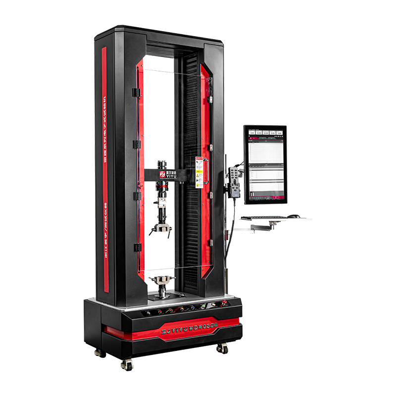
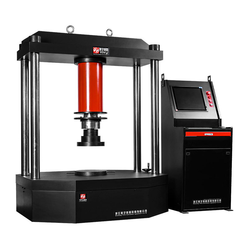
An electronic universal testing machine (UTM) is a servo-motor-driven system that applies controlled tensile, compression, flexural, or shear force to a material specimen while an electronic load cell and displacement encoder record data to determine mechanical properties such as tensile strength, yield point, and elastic modulus. Unlike hydraulic testing machines, electronic UTMs use an AC servo motor and precision ball screw to move the crosshead, giving them tighter speed control and cleaner low-force measurement — which is why they dominate metals, plastics, textile, and composite testing labs today.
The sections below cover how these machines actually work, what the key specifications mean in practice, how to size and select one correctly, and which standards govern their calibration and use.
How an Electronic Universal Testing Machine Works
The operating principle is straightforward even though the components are precise. An AC servo motor drives a ball screw, which raises or lowers the crosshead at a controlled speed. A linear encoder tracks crosshead position in real time, feeding that data back into a closed-loop control system so the machine can hold an exact speed, force, or strain rate throughout the test.
As the specimen is stretched, compressed, or bent, a load cell mounted in the load train measures the resisting force electronically, while the encoder or an attached extensometer measures deformation. Both signals are captured simultaneously and plotted as a stress-strain curve, from which the software automatically calculates properties like ultimate tensile strength, 0.2% offset yield strength, elongation, and modulus.
This closed-loop design is what allows electronic UTMs to switch between control modes mid-test:
- Crosshead speed control — constant displacement rate, the most common mode for general tensile and compression tests
- Strain rate control — uses extensometer feedback to hold a precise strain rate, required by standards like ASTM E8 for metals
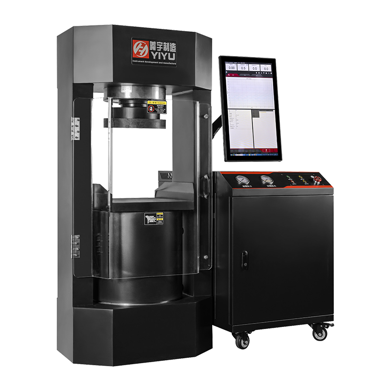
- Load/stress rate control — increases force at a constant rate, common for brittle materials and concrete testing
Core Components That Determine Test Quality
Every electronic UTM is built from a consistent set of subsystems, and the quality of each one directly affects how trustworthy the resulting data is.
Core components of an electronic universal testing machine
| Component |
Role |
| Load frame |
Provides rigid structure; single-column for low force, double-column (H-frame) for higher force |
| AC servo motor and ball screw |
Drives crosshead movement with precise, repeatable speed control |
| Load cell |
Electronically measures applied force; accuracy is classified per ISO 7500-1 |
| Extensometer |
Measures specimen deformation directly, excluding machine compliance |
| Grips and fixtures |
Hold the specimen; wedge grips for metals, pneumatic grips for plastics, platens for compression |
| Control software |
Runs test methods, calculates results, and generates compliance reports |
Electronic vs. Hydraulic Universal Testing Machines
The two dominant UTM architectures serve different needs, and the choice mostly comes down to force range and the type of control precision required.
Electronic (Electromechanical) Machines
Typical load capacity ranges from 0.5 kN to 300 kN, with speed ranges from 0.001 to 1000 mm/min and position resolution of 0.001 mm or better. Their main advantage is precise, quiet, low-maintenance speed control, which is why standards like ASTM E8 that mandate strict strain rate compliance are easiest to satisfy on electromechanical frames. Typical accuracy is ±0.5% of load cell capacity (ISO 7500-1 Class 0.5).
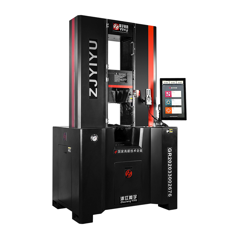
Hydraulic (Servo-Hydraulic) Machines
Typical load capacity ranges from 100 kN to 2000 kN, making them the standard choice for high-force applications like structural steel, large rebar, or concrete testing. They offer stable force control for creep and fatigue testing but require periodic seal replacement and hydraulic fluid maintenance, and typically run at Class 1.0 accuracy with higher noise levels (75-85 dB).
Laboratories that need both very low force sensitivity for thin films and very high force capacity for metals often maintain two machines rather than one, since a single oversized frame can lack the load cell sensitivity needed to capture subtle behavior in delicate specimens.
How to Select the Right Load Capacity
Capacity selection is the single most consequential decision when specifying a UTM, and it's also where buyers most often overspend or underspend.
The general rule is to choose a UTM so the expected peak test force falls between 20% and 80% of the load cell's rated capacity. Outside that window, results become inaccurate at the low end, or the load cell risks damage at the high end. A useful worked example: testing ASTM C39 concrete cylinders at 150 mm diameter with 50 MPa strength requires roughly 880 kN of force, which means a 1000 kN load cell is the appropriate selection rather than anything smaller.
- Identify the strongest material and largest specimen cross-section you expect to test.
- Calculate the maximum force that specimen could generate at its ultimate strength.
- Apply a safety margin, generally 20-30% above that maximum, rather than jumping to the largest available frame.
- Cross-check against the applicable test standard, since some standards specify minimum capacity or accuracy class requirements directly.
Standards That Govern Electronic UTMs
Test results are only defensible if the machine and method are traceable to a recognized standard. Different materials and test types map to different standards, and a lab serving multiple markets often needs to satisfy several at once.
- ASTM E4 / ISO 7500-1 — force calibration and verification of the testing machine itself, typically required annually
- ASTM E8 / ISO 6892-1 — tensile testing of metallic materials, including required strain rate control
- ASTM D638 / ISO 527 — tensile properties of rigid plastics
- ASTM D882 — tensile testing of thin plastic films
- ASTM E9 / ISO 604 — compression testing of metals and plastics, respectively
- ASTM C39 — compressive strength of concrete cylinders
Load cell accuracy itself is classified under ISO 7500-1 into Class 0.5, 1.0, or 2.0, corresponding to maximum permissible error of 0.5%, 1.0%, or 2.0% of indicated force. Most tensile testing on metals and plastics requires Class 0.5 or better, while higher-force compression testing can often tolerate Class 1.0.
Calibration and Maintenance Requirements
An electronic UTM's electronic load cell and encoder drift over time, so ongoing calibration isn't optional if results are being used for compliance, certification, or accreditation purposes.
Annual calibration is the standard minimum interval, performed as a five-point check at 20%, 40%, 60%, 80%, and 100% of rated capacity, using a reference standard traceable to a national metrology institute such as NIST, PTB, or NIM. High-volume laboratories often add interim checks every three to six months between full calibrations. Any overload event above roughly 110% of load cell capacity should trigger a re-verification, since even a brief overload can shift load cell linearity enough to affect subsequent results.
Routine mechanical upkeep matters just as much as calibration:
- Inspect and clean grips after each use to remove debris that can affect alignment
- Verify load cell zero calibration if results appear to drift by more than about 1%
- Lubricate the ball screw and other moving parts on a scheduled basis
- Confirm grip and specimen alignment periodically, since excessive bending strain invalidates tensile results
With this level of care, a quality electronic UTM typically has a service life of 15 to 25 years, with the mechanical frame usually outlasting the electronics and control software.
Common Applications by Industry
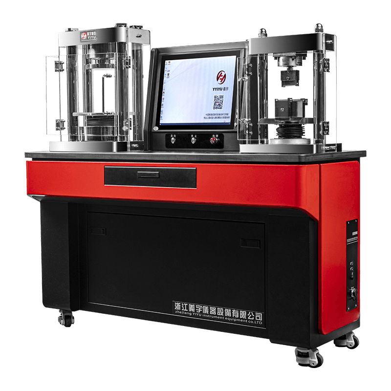
Because a single electronic UTM can switch between tensile, compression, flexural, peel, and shear testing simply by changing fixtures, it's used across a wide range of industries rather than being confined to one material type.
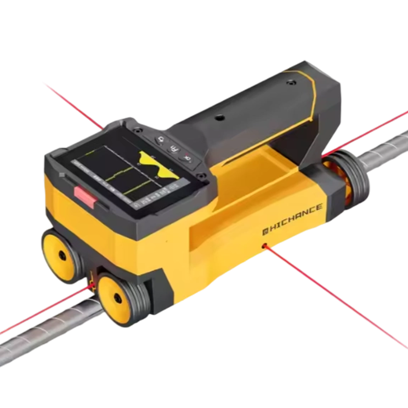
- Metals and construction — tensile and yield testing of steel plate, rebar, and structural components
- Plastics and packaging — tensile properties of films, rigid plastics, and seal/peel strength of packaging materials
- Medical devices — mechanical characterization of components like syringe barrels and biocompatible plastics
- Aerospace — flexural modulus and strength validation of high-strength composites such as carbon fiber
- Textiles and electronics — strip tensile testing of fabrics and cable tensile strength verification
Frequently Asked Questions
What's the difference between a load cell's capacity and the accuracy it delivers?
Capacity is the maximum force the load cell can measure, while accuracy (expressed as a class per ISO 7500-1) is how close the reading is to the true force, and accuracy is generally only reliable within the 20-80% portion of that rated capacity.
Do I need an extensometer for every test?
Not for every test, but it's required whenever a standard calls for accurate elastic modulus or precise yield point determination, since crosshead displacement alone includes machine compliance and isn't an accurate measure of specimen deformation.
Can one electronic UTM really replace several dedicated testing machines?
Yes, within its force and speed range — the frame, load cell, and software stay the same, and only the fixtures change between tensile, compression, and flexural testing, which is the core appeal of the "universal" design.
How long does it take to train an operator on a UTM?
Basic operation can be learned in one to two days, but producing reliable, standard-compliant results typically requires one to two weeks of deeper training, and operator competence should be documented for accredited laboratories.
 简体中文
简体中文
 English
 русский