When you need to guarantee that a steel bar will hold up under a bridge’s load, or that a plastic component won’t crack during assembly, you turn to a single piece of equipment: the universal testing machine (UTM). Instead of guessing or relying on theoretical numbers, the UTM physically pulls, pushes, bends, or shears a sample until it breaks—recording exactly how much force it can withstand and how much it deforms before failure. This direct, quantitative measurement is the bedrock of material quality control in industries from construction to aerospace.
Core Components of a Universal Testing Machine
Understanding how a UTM works starts with knowing the main parts that work together to apply and measure forces. Every commercial UTM, whether it uses a hydraulic or electromechanical drive, shares these fundamental elements:
Load Frame
The load frame is the rigid structure that holds everything together. It consists of two vertical support columns, a fixed base, and a movable crosshead. The frame must be stiff enough to absorb the reaction forces without bending, ensuring that the measured force reflects only what the specimen experiences. Frames come in single‑column tabletop designs for small loads (up to 5 kN) and dual‑column floor‑standing models for capacities exceeding 1000 kN.
Crosshead and Actuator
The crosshead moves vertically to apply the test force. In electromechanical UTMs, a servo‑motor turns a ball screw to move the crosshead with precise speed control. In hydraulic UTMs, an actuator driven by high‑pressure oil pushes the crosshead. The crosshead speed can be set from a few micrometers per second to hundreds of millimeters per minute, depending on the test standard.
Load Cell
The load cell is the sensor that converts mechanical force into an electrical signal. It sits between the moving crosshead and the grip holding the specimen. Load cells are calibrated in full‑scale ranges (e.g., 10 kN, 100 kN, 600 kN) and must be selected so that the expected test force falls between 10 % and 90 % of the cell’s capacity for the best accuracy. Many modern UTMs can automatically switch between multiple load cells to handle both delicate films and heavy steel bars on the same frame.
Grips and Fixtures
Grips hold the specimen securely during testing. The type of grip depends on the test method: wedge grips for tensile tests on flat or round samples, compression platens for crushing tests, bending fixtures for flexure tests, and specialized accessories for shear, peel, or puncture tests. Poor gripping can cause slipping or premature failure, so matching the grip to the material and geometry is critical.
Extensometers and Displacement Sensors
To measure how much the specimen stretches or compresses, UTMs use extensometers that clip directly onto the sample. These sensors track strain with micron precision. For tests where the machine crosshead displacement is acceptable (e.g., compression of rigid blocks), an internal encoder on the actuator provides position feedback. Accurate strain measurement is essential for calculating Young’s modulus, yield strength, and elongation.
Control System and Software
A dedicated controller receives signals from the load cell and extensometer, compares them to the command values (force, speed, position), and adjusts the actuator in real time. The software on the attached computer allows the operator to define test methods (ASTM, ISO, GB/T), control the machine, and view live curves. After the test, the software automatically computes parameters like ultimate tensile strength, yield point, and break energy, and generates a report.
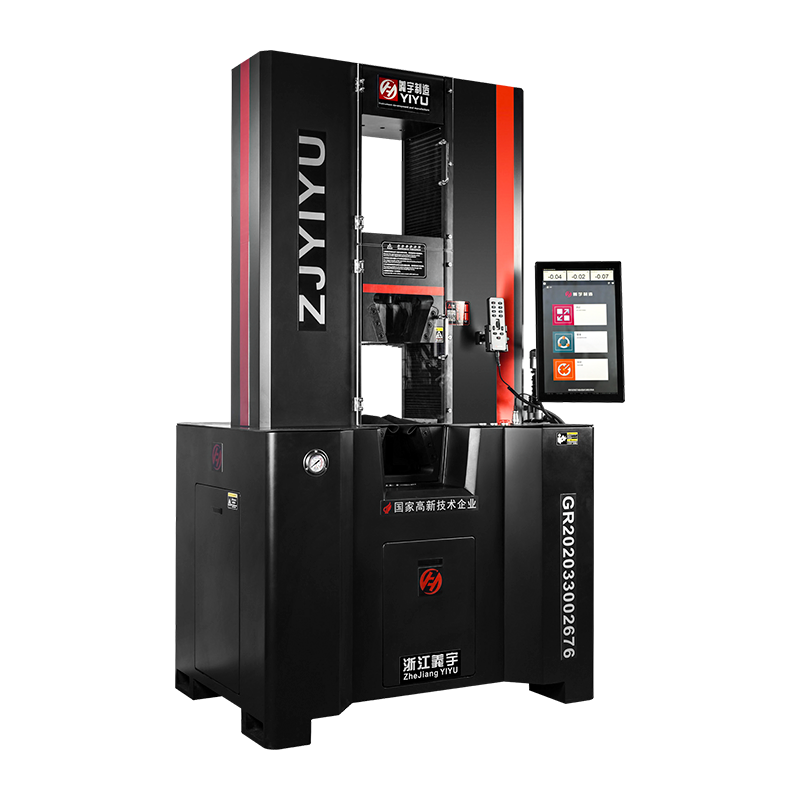
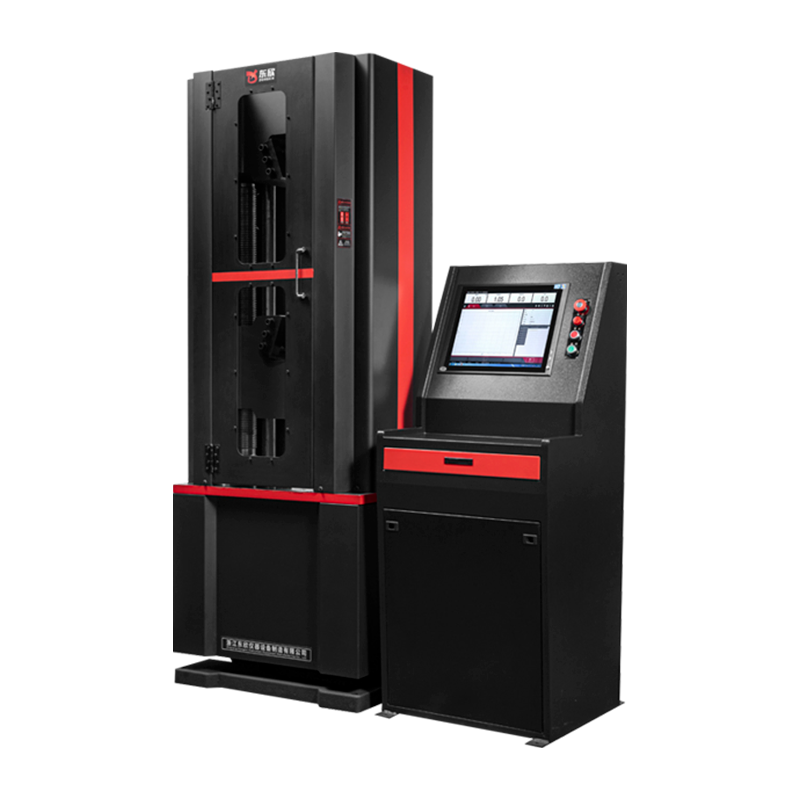 WAW-100/300/600/1000B Microcomputer-Controlled Electro-Hydraulic Servo UTMThis high-rigidity six-column UTM integrates intelligent servo control and precision measurement (Class 1 accuracy), making it ideal for automated high-load tests with real-time curve monitoring and automatic parameter calculation.View Product →
How the Testing Process Works: Step by Step
The operating sequence of a UTM is straightforward, but each step requires attention to detail to produce repeatable, standard‑compliant results.
Step 1: Specimen Preparation and Measurement
Before loading, the specimen must be prepared according to the relevant standard (e.g., ASTM E8 for metals, ASTM D638 for plastics). This means cutting or machining the sample to specified dimensions, conditioning it at a controlled temperature and humidity if required, and measuring its initial cross‑sectional area and gauge length with a micrometer or caliper. These dimensions will be entered into the software so that stress (force/area) and strain (change in length/original length) can be calculated.
Step 2: Mounting the Specimen
The operator selects the correct grips and attaches them to the load frame. The specimen is then aligned and clamped. For tensile tests, care must be taken to center the specimen in the grips to avoid bending moments. For compression tests, the specimen is placed between two hardened platens; the top platen is lowered until it just touches the sample, and a small pre‑load (typically less than 10 % of the expected test load) is applied to ensure full contact.
Step 3: Setting Test Parameters
Using the control software, the operator chooses the test type (tension, compression, flexure, etc.), the force or displacement rate (e.g., 2 mm/min for a metal tensile test), the end condition (break, maximum force, or a defined deformation limit), and the data acquisition rate. Modern UTMs store hundreds of standard methods, so the operator may simply load a predefined recipe.
Step 4: Running the Test
Once started, the crosshead moves at the programmed speed. The load cell continuously measures the force, and the extensometer measures the elongation. The software plots the force‑displacement or stress‑strain curve in real time. During the test, the operator can monitor the curve and stop early if there are signs of grip slippage or unexpected behavior. When the specimen fails (or the end condition is met), the crosshead stops automatically and returns to its starting position.
Step 5: Data Analysis and Reporting
The software immediately calculates key mechanical properties from the recorded curve: yield strength (by the offset method or visual determination), ultimate tensile strength (the highest point on the curve), elongation at break, and reduction of area. For compression tests, the compressive strength and modulus are computed. The results can be exported as PDF or CSV, stored in a database, or printed as a test certificate. This analysis is what makes the UTM invaluable for quality assurance—it turns raw sensor data into actionable pass/fail evidence.
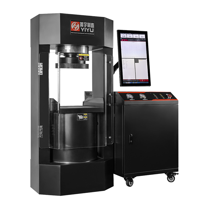
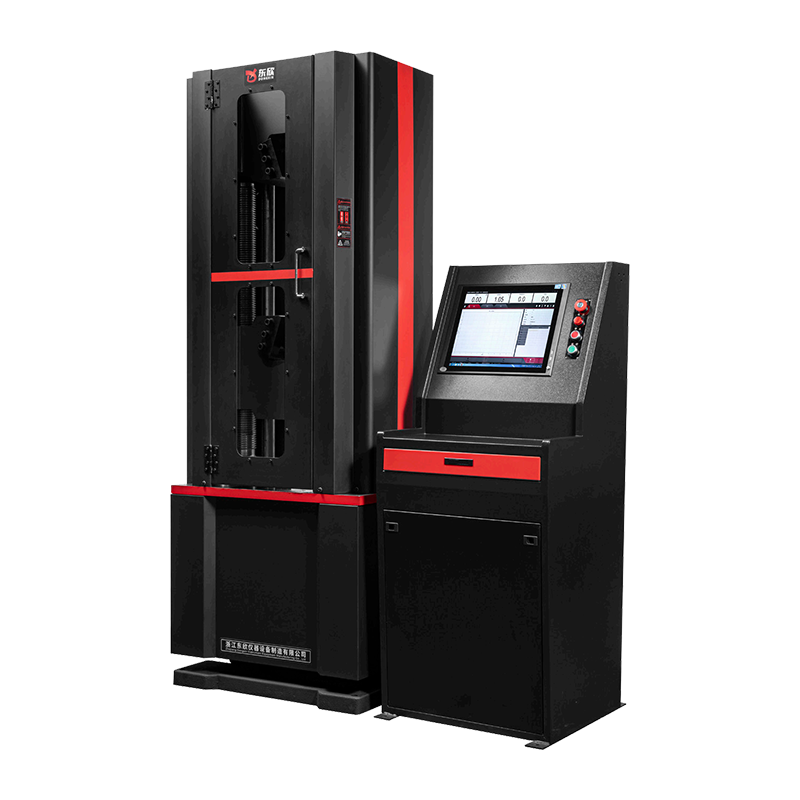 WAW-600/1000G Electro-Hydraulic Servo UTM for Steel Bars and StrandsDesigned as a dual-purpose machine for steel bars and strands, this model offers single-space operation and precise closed-loop control, enabling direct calculation of yield strength, tensile strength, and elongation from test data.View Product →
For a deeper look at practical test setups, including troubleshooting common issues, refer to the comprehensive hydraulic UTM operation guide.
Why Understanding the Working Principle Matters for Your Lab
Knowing exactly how a UTM works isn’t just academic—it directly impacts the reliability of your test results and your ability to select the right machine for your applications.
Accuracy and Repeatability
Every component in the force measurement chain—load cell, amplifier, analog‑to‑digital converter—contributes a potential error. Understanding the principle allows you to specify the correct load cell class (ISO 7500‑1 class 0.5 or 1) and to set up periodic calibrations. Similarly, the crosshead speed must be verified because many material properties are strain‑rate‑sensitive. A UTM that maintains consistent speed regardless of load changes is essential for standards like ASTM D638 (plastics) where the test speed is specified to within ±1 %.
Choosing Between Hydraulic and Electromechanical Systems
The working principle defines the machine’s performance envelope.
- Hydraulic UTMs (like the WAW series) use a servo‑valve and oil pump to generate very high forces (500 kN to 2000 kN or more). They excel in testing rebar, structural steel, and concrete blocks where force requirements are large and test speeds can be fast. However, hydraulic systems have slower control response and are less suited for low‑force, high‑precision measurements.
- Electromechanical UTMs (like the WDW series) use a servo‑motor and ball screw, offering superior speed accuracy and lower noise. They are ideal for plastics, composites, thin films, and elastic materials where the test force stays below 50 kN and fine control of displacement is critical.
Many modern labs maintain both types to cover their full testing range. For a comparison of the two drive technologies in real‑world scenarios, the Yiyu instrumentation guide provides further insight.
Integration with Automation and Data Management
A clear understanding of the UTM’s working cycle—specimen loading, force application, data acquisition, crosshead return—enables you to automate repetitive tests. Some machines support robotic arm loading and unattended testing of hundreds of samples. The resultant data can be fed directly into a laboratory information management system (LIMS) for traceability and statistical process control. This capability is increasingly demanded by automotive and aerospace suppliers who must provide batch‑level quality records.
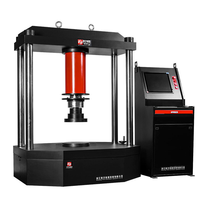
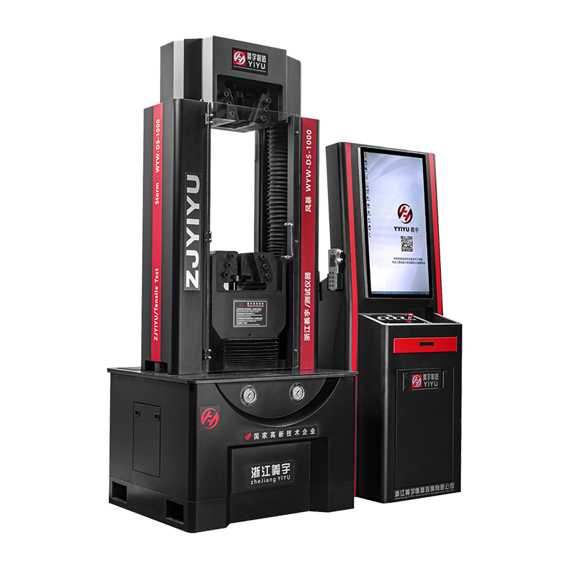 WYW-DS Series Vibration-Free Microcomputer-Controlled Electro-Hydraulic Servo UTMFeaturing a patented vibration-free base and high-rigidity six-column frame, this UTM supports robotic automation and LIMS integration, ensuring stable high-load testing without requiring a dedicated foundation.View Product →
From the initial setup to the final report, every stage of a UTM test relies on the precise interaction of mechanical, electrical, and software components. By understanding how load is applied, measured, and analyzed, you can troubleshoot irregularities, optimize test methods, and confidently certify that your materials meet the required specifications. Whether you are evaluating steel reinforcement for a high‑rise tower or checking the peel strength of an adhesive joint, the universal testing machine remains the most versatile and trusted tool in material testing.

 简体中文
简体中文
 English
 русский