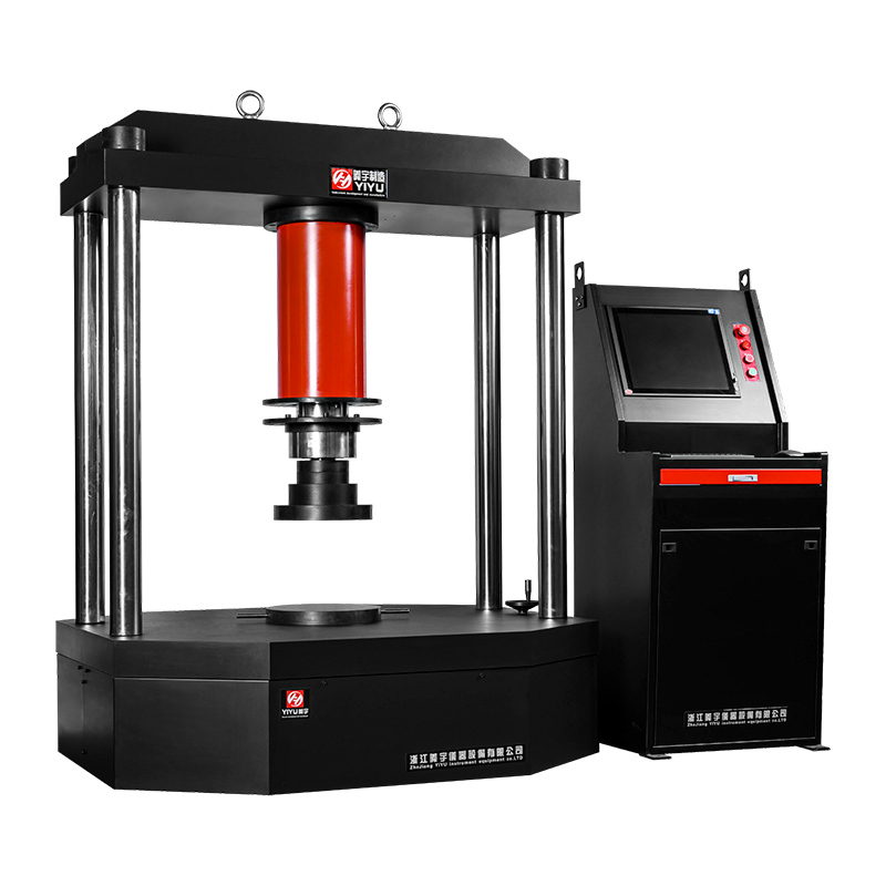
A hydraulic universal testing machine (UTM) is a materials testing instrument that uses hydraulic force generation to apply controlled tensile, compressive, flexural, shear, and bend loads to test specimens — measuring their mechanical properties under those loads. Hydraulic UTMs are the standard choice for high-force testing applications, with capacities typically ranging from 100 kN to 3,000 kN (10 to 300 tonnes), making them essential equipment in steel mills, construction material laboratories, aerospace component qualification, and heavy manufacturing quality control.
The global materials testing equipment market exceeded $800 million in 2023, with hydraulic UTMs representing the dominant technology for force capacities above 100 kN. For laboratory managers, quality engineers, procurement specialists, and materials scientists, understanding the operating principles, key specifications, test capabilities, and selection criteria of hydraulic UTMs is fundamental to making sound equipment investments and producing reliable test data.
How a Hydraulic Universal Testing Machine Works
A hydraulic UTM generates force by pressurizing hydraulic fluid — typically mineral oil — and directing that pressure against a hydraulic cylinder piston. The resulting piston movement applies force to a crosshead, which in turn loads the test specimen through the appropriate grips or fixtures.
The Hydraulic Drive System
The hydraulic system consists of a motor-driven pump that pressurizes oil in a closed circuit. A servo valve or proportional control valve regulates the flow of oil to the main cylinder — controlling both the direction of crosshead movement (up or down) and the rate of force application. The relationship between hydraulic pressure and applied force follows directly from Pascal's Law: Force = Pressure × Piston Area. A cylinder with a 100cm² piston area at 300 bar (30 MPa) system pressure delivers 300,000 N (300 kN) of force.
Servo-Hydraulic vs. Conventional Hydraulic Control
Modern hydraulic UTMs use one of two control approaches:
- Conventional hydraulic (open-loop): A manually or semi-automatically adjusted proportional valve controls oil flow. Suitable for standard static testing where precise load ramp rates are not critical. Lower cost, simpler maintenance.
- Servo-hydraulic (closed-loop): A high-response servo valve receives real-time feedback from load cells, extensometers, or displacement transducers and continuously adjusts oil flow to maintain the programmed test condition (constant load rate, constant strain rate, or constant displacement rate). Required for standards-compliant testing under ISO 6892, ASTM E8, and EN 10002. Capable of load control accuracy of ±0.5% of indicated value.
Frame Structure and Load Path
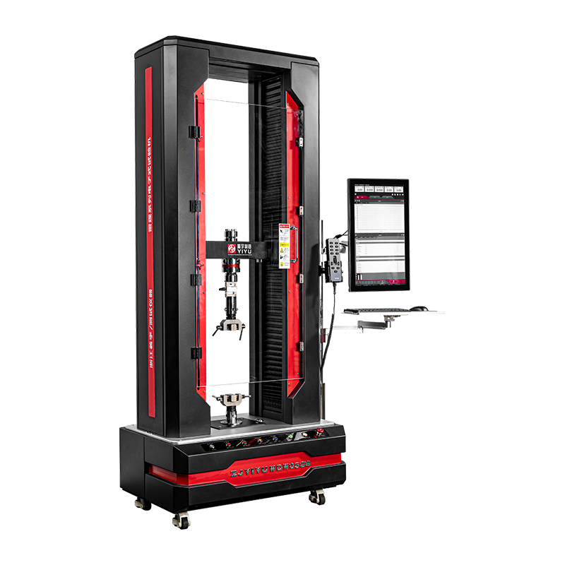
The machine frame provides the structural loop through which test forces are reacted. Most hydraulic UTMs use a two-column or four-column design with a fixed lower table, a moving crosshead driven by the hydraulic cylinder, and a fixed upper crosshead. The test specimen is gripped between the moving and fixed crossheads. The columns must be rigid enough to deflect less than the specimen's elongation under maximum test load — frame stiffness is typically specified as a maximum deflection of 1–3 mm at full rated capacity.
Key Technical Specifications of Hydraulic UTMs
Evaluating a hydraulic UTM requires understanding a specific set of technical parameters. Each specification directly affects the machine's suitability for particular test types and compliance with testing standards.
Key hydraulic UTM specifications and their significance for test capability and standards compliance
| Specification |
Typical Range |
Why It Matters |
| Force capacity (rated load) |
100 kN – 3,000 kN |
Must exceed maximum expected specimen failure load by safety margin |
| Load measurement accuracy |
±0.5% – ±1.0% of indicated value |
Determines compliance with ISO 7500-1 Class 1 or Class 0.5 |
| Crosshead speed range |
0.1 – 200 mm/min |
Must match standard-specified strain rate for material type |
| Daylight (test space) |
500 – 1,500 mm |
Must accommodate longest specimen plus grip length |
| Piston stroke |
200 – 800 mm |
Limits maximum specimen elongation measurable |
| Position resolution |
0.001 – 0.01 mm |
Affects displacement measurement accuracy for modulus calculation |
| Hydraulic system pressure |
200 – 350 bar |
Determines force achievable for a given cylinder bore |
| Load measurement ranges |
Typically 4 ranges (e.g., 1/10/100/1000 kN) |
Lower ranges improve accuracy for weaker specimens on high-capacity machines |
Force Capacity Selection
Selecting the correct capacity is critical. The machine should be sized so that specimen failure loads fall within 20–80% of the machine's full scale range — this ensures measurement accuracy is within the calibrated working range of the load cell. Testing a 50 kN specimen on a 1,000 kN machine at 5% of full scale produces unreliable data. Most hydraulic UTMs address this through multiple load ranges with dedicated load cells or switchable amplifier ranges.
Types of Tests Performed on Hydraulic UTMs
The "universal" in universal testing machine refers to the machine's ability to perform multiple test types by reconfiguring grips, fixtures, and load application geometry. Hydraulic UTMs handle the full spectrum of mechanical tests across metals, polymers, composites, concrete, timber, and geotechnical materials.
Tensile Testing
Tensile testing is the most common application for hydraulic UTMs. A specimen — typically a dog-bone or rectangular flat profile for metals and plastics, or a full-section coupon for construction materials — is gripped at both ends and pulled apart at a controlled crosshead speed. The test measures:
- Ultimate tensile strength (UTS): The maximum stress the material sustains before fracture.
- Yield strength (0.2% proof stress): The stress at which permanent plastic deformation begins — typically the most design-critical property for structural metals.
- Young's modulus (elastic modulus): The slope of the linear elastic portion of the stress-strain curve, measured with an extensometer attached directly to the specimen.
- Elongation at break (ductility): The percentage increase in gauge length at fracture — a measure of material ductility critical for forming operations.
- Reduction of area: The percentage reduction in cross-sectional area at the fracture point.
Compression Testing
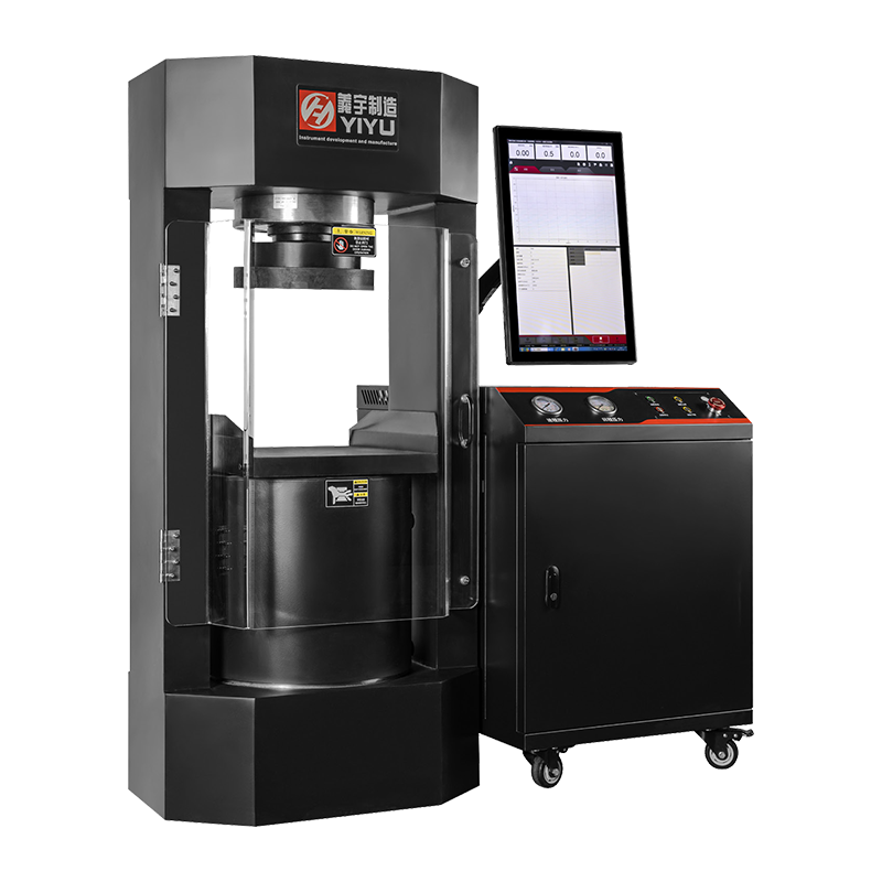
Compression testing uses flat platens to apply compressive load to a specimen — most commonly concrete cylinders (150mm × 300mm or 100mm × 200mm per EN 12390-3 and ASTM C39), masonry blocks, timber samples, or metallic specimens. For concrete quality control in construction, compression testing is the single most frequently performed structural material test worldwide. Standard concrete cube crushing tests require machines with capacities of 2,000–3,000 kN (200–300 tonnes).
Flexural (Bend) Testing
Three-point and four-point bend tests apply load through roller supports to evaluate flexural strength, flexural modulus, and deflection behavior. Common applications include concrete beam flexural strength (ASTM C78, EN 12390-5), reinforcing bar bend tests, timber floor joist capacity evaluation, and composite panel stiffness assessment. Large hydraulic UTMs with wide platens and long test spans are required for structural member testing.
Rebar and Wire Rope Testing
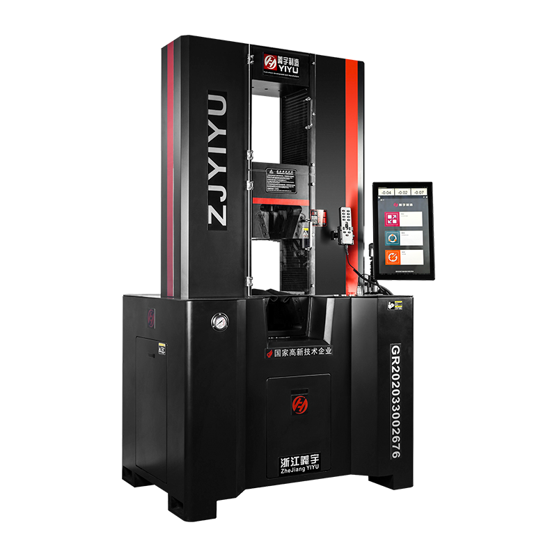
Testing of reinforcing steel (rebar) to ISO 15630, ASTM A615, or BS 4449 standards is one of the most common hydraulic UTM applications in construction quality control. Rebar in sizes from 6mm to 50mm diameter requires tensile test forces of 20 kN to over 2,000 kN — a range that spans multiple machine capacities. Wedge-action grips are the standard fixture for rebar tensile testing, providing self-tightening grip action proportional to applied tensile load.
Shear and Peel Testing
Specialized fixtures enable shear lap testing of adhesive bonds, welds, and riveted joints, as well as peel testing of laminates and coatings. These tests are essential in automotive panel bonding qualification, aircraft structure certification, and advanced composite manufacturing quality control.
Hydraulic UTM vs. Electromechanical UTM: When to Choose Each
Hydraulic and electromechanical (EM) UTMs address different segments of the force range and test type spectrum. Understanding their comparative strengths prevents over-investment in hydraulic technology where EM would suffice — and avoids under-specifying when hydraulic force generation is genuinely required.
Direct comparison of hydraulic and electromechanical UTMs across key performance and operational criteria
| Criterion |
Hydraulic UTM |
Electromechanical UTM |
| Maximum force capacity |
Up to 3,000 kN+ (practical no upper limit) |
Typically up to 600 kN; some to 2,000 kN |
| Low-force precision |
Limited — hydraulic friction and oil viscosity effects |
Excellent — leadscrew/ballscrew precision |
| Crosshead speed range |
0.5 – 200 mm/min typical |
0.0001 – 1,000+ mm/min |
| Maintenance requirements |
Higher — oil changes, seals, pump service |
Lower — primarily electrical components |
| Energy consumption |
Higher (pump runs continuously) |
Lower (motor draws power only during crosshead movement) |
| Initial cost |
Lower at high capacities (>200 kN) |
Lower at low-medium capacities (<200 kN) |
| Best application domain |
Steel, concrete, rebar, heavy structural testing |
Polymers, thin metals, medical devices, precision testing |
The crossover point where hydraulic technology becomes the more practical choice is generally above 200–300 kN (20–30 tonnes). Below that, electromechanical UTMs provide better displacement control, lower maintenance costs, and wider speed range for the same investment. Above 300 kN, hydraulic systems are significantly more compact and cost-effective than the large ballscrew assemblies required for high-force EM machines.
Grips and Fixtures: Matching Accessories to Test Requirements
A hydraulic UTM without the correct grips and fixtures cannot perform valid tests. The grip must hold the specimen rigidly without slipping (which causes premature failure data), without over-stressing the grip zone (which causes grip-induced failures invalidating the test), and without introducing bending moments into what should be a purely axial load.
Wedge-Action Grips
Wedge-action grips are the most common tensile grip type for hydraulic UTMs. As tensile load increases, the wedge mechanism drives the grip faces tighter onto the specimen — providing self-tightening clamping proportional to applied force. They are suitable for flat specimens, round bar, rebar, wire, and cable testing. Interchangeable jaw inserts with different serration patterns (coarse for steel, smooth for softer materials) expand versatility. Hydraulic wedge grips (pneumatically or hydraulically actuated specimen clamping) eliminate inconsistent manual tightening and are standard on high-volume production testing lines.
Compression Platens
Hardened steel compression platens with a spherical seating (self-aligning) top platen are the standard fixture for concrete, mortar, masonry, and ceramic compression testing. The spherical seat compensates for minor specimen non-parallelism, ensuring uniform load distribution across the full specimen cross-section as required by EN 12390-3 and ASTM C39. Platen hardness must meet Rockwell C 55 minimum per most standards to prevent platen indentation affecting results.
Bend and Flexure Fixtures
Three-point and four-point bend fixtures consist of hardened steel rollers mounted on adjustable supports. Roller diameter and support span are specified by the applicable standard — for example, EN ISO 7438 specifies specific mandrel diameters for metal bend tests as a function of material thickness and bend angle. Incorrect roller size or span invalidates the test and produces non-comparable results.
Extensometers
Crosshead displacement measured by the machine's position transducer includes compliance of the frame, grips, and load train — introducing significant error into strain and modulus calculations. A clip-on extensometer attached directly to the gauge length of the specimen measures true specimen strain independently of machine compliance, which is mandatory for accurate Young's modulus determination per ISO 6892-1 and ASTM E8. Extensometer gauge lengths are standardized — typically 50mm or 80mm for metals — and must match the specimen gauge length specified in the test standard.
Relevant Testing Standards for Hydraulic UTMs
Hydraulic UTM operations in quality control, certification testing, and research are governed by a hierarchy of standards — machine verification standards that define acceptable machine performance, and material test method standards that specify exactly how each test must be conducted.
Machine Verification Standards
- ISO 7500-1: Verification and calibration of static uniaxial testing machines for metals. Defines Class 0.5, Class 1, and Class 2 accuracy classifications (±0.5%, ±1.0%, ±2.0% force measurement error at each calibrated range). Most materials certification work requires Class 1 minimum.
- ASTM E4: Standard practices for force verification of testing machines. The U.S. equivalent to ISO 7500-1, specifying ±1% force accuracy across the working range.
- EN ISO 9513: Calibration of extensometers used in uniaxial testing — defines Class 0.5, 1, and 2 extensometer accuracy requirements.
Material Test Method Standards
- ISO 6892-1 / ASTM E8: Tensile testing of metallic materials at ambient temperature. Specifies specimen geometry, crosshead speed, extensometer requirements, and data reporting.
- EN 12390-3 / ASTM C39: Compressive strength testing of concrete specimens. Specifies loading rate (0.6 ± 0.2 MPa/s per EN 12390-3), platen requirements, and reporting.
- ISO 15630-1 / ASTM A615: Testing requirements for reinforcing steel (rebar) — tensile strength, yield strength, elongation, and bend test requirements.
- ISO 178 / ASTM D790: Flexural properties of plastics and composite materials by three-point bend testing.
- EN 408 / ASTM D143: Mechanical properties of structural timber and wood-based products.
Calibration and Verification of Hydraulic UTMs
Calibration is not optional for hydraulic UTMs used in quality assurance, product certification, or compliance testing — it is a legal and contractual requirement. The consequences of operating an out-of-calibration machine include issuing invalid test certificates, failing product audits, and liability exposure if certified materials fail in service.
Calibration Frequency
ISO 7500-1 recommends annual calibration as a minimum — more frequently if the machine is subject to heavy use, has been relocated, repaired, or shows drift in repeat measurements. Most accredited testing laboratories performing ISO/IEC 17025-certified testing calibrate their UTMs at least annually and after any maintenance affecting the load train.
Calibration Method
Calibration is performed by applying known reference forces to the machine using either:
- Deadweight calibration machines: The most traceable method — known masses apply gravity forces directly. Used for machines up to approximately 5,000 kN in national metrology institutes.
- Reference load cells (transfer standards): A NIST-traceable or UKAS-accredited reference load cell is mounted in the machine's load train and the UTM's indication is compared to the reference at multiple force levels. The most practical field calibration method for large machines. Reference load cells are typically calibrated to 0.1% accuracy or better, providing sufficient margin over the 0.5% Class 1 machine specification.
Verification vs. Calibration
Calibration adjusts the machine's force indication to match reference standards. Verification (per ISO 7500-1) confirms that the machine meets its accuracy class specification without necessarily adjusting it. Both processes generate a certificate with documented results. Calibration certificates must include expanded measurement uncertainty (typically at 95% confidence level) to be compliant with ISO/IEC 17025 requirements for accredited test laboratories.
Maintenance of Hydraulic UTMs: Critical Practices
Hydraulic UTMs require more active maintenance than electromechanical machines due to their oil-based drive system. A structured maintenance program prevents unexpected downtime, protects calibration status, and extends machine service life — machines maintained to schedule routinely operate for 20–30 years or more.
Hydraulic Oil Management
Hydraulic oil degrades through oxidation, moisture absorption, and particle contamination. Contaminated oil causes accelerated wear of servo valves, cylinder seals, and pump components. Key oil maintenance practices:
- Annual oil analysis: Send oil samples to a laboratory for viscosity, water content, and particle count analysis. ISO cleanliness target of ISO 4406 Class 16/14/11 or better for servo-hydraulic systems.
- Oil and filter change interval: Replace hydraulic oil every 2–4 years or per manufacturer schedule; replace return and pressure filters at each oil change and when differential pressure indicators trigger.
- Breather filter maintenance: The reservoir breather prevents atmospheric contamination — replace annually or when visually contaminated.
Seal and Cylinder Inspection
Main cylinder piston seals, rod seals, and servo valve seals require periodic inspection and replacement. Oil weeping from the cylinder rod is an early indicator of seal wear — address before the leak becomes significant enough to affect force measurement accuracy or create slip hazards. Typical seal service interval is 5–10 years depending on cycle frequency and operating pressure.
Load Cell and Transducer Care
Load cells must never be subjected to shock overloads — sudden specimen fracture transmits a dynamic impact force that can permanently damage strain gauge elements. Always use machines with overload protection set to 110–120% of rated capacity. Inspect load cell cable connections regularly; corroded or intermittent connections cause erratic force readings that are difficult to diagnose. Store spare load cells in a dry environment to prevent moisture ingress into the strain gauge circuit.
How to Select the Right Hydraulic UTM: Decision Criteria
Purchasing a hydraulic UTM is a significant capital investment — machines typically cost $15,000 to $250,000+ depending on capacity, control sophistication, and included fixtures. A structured selection process prevents both over-specification (paying for capability that will never be used) and under-specification (buying a machine that cannot perform the required tests to the required standard).
- Define the full scope of tests required now and in the foreseeable future. List every material type, specimen geometry, force range, and applicable test standard. A machine selected for rebar testing today may need to test structural steel weldments tomorrow — build in appropriate capacity and daylight margin.
- Determine the maximum force required with margin. Identify the single largest force test in your scope, add a 25–40% safety margin, and select the machine capacity at or above that value. Do not undersize to save money — a machine that cannot reach the required force provides no test data at all.
- Specify the required accuracy class. If your work involves product certification, third-party audits, or test reports used in structural design, specify ISO 7500-1 Class 1 minimum. Research applications may tolerate Class 2.
- Evaluate control sophistication needed. Simple concrete cube crushing requires only basic load-controlled operation. Metal tensile testing to ISO 6892-1 Method A requires servo-controlled strain rate capability. Confirm the control system can execute the required test protocols before purchasing.
- Assess software and data output requirements. Modern UTM software should generate test reports directly compliant with the relevant standard's reporting requirements, export to LIMS (Laboratory Information Management Systems), and support data traceability with operator login, specimen ID, and timestamp logging.
- Evaluate total cost of ownership, not just purchase price. Factor in oil consumption, filter costs, calibration fees, expected seal replacement intervals, and service contract costs over a 10-year operating horizon. A machine with lower initial cost but higher annual maintenance expense may cost more in total.
- Verify local service support availability. A hydraulic UTM that breaks down with no local service engineer available disrupts production testing operations. Confirm the supplier has certified service engineers within acceptable response time distance before committing.
 简体中文
简体中文
 English
 русский