A universal testing machine (UTM) is a mechanical testing instrument capable of applying controlled tensile, compressive, flexural, shear, and bend forces to a material specimen in order to measure its mechanical properties — most commonly tensile strength, yield strength, elongation, and elastic modulus. The word "universal" refers to its ability to perform multiple types of mechanical tests on a single frame by changing the test fixtures, not to unlimited capacity. Load capacities range from under 1 kN for delicate materials such as films and fibres to over 2,000 kN for structural steel and concrete components.
Universal tensile test equipment is used across virtually every manufacturing and research sector — metals, polymers, composites, textiles, rubber, adhesives, construction materials, medical devices, and packaging — wherever quantitative data on how a material behaves under mechanical load is required for design, quality control, or regulatory compliance.
How a Universal Testing Machine Works
The fundamental operating principle of a UTM is simple: a specimen is gripped between two fixtures — one fixed and one moving — and a controlled force is applied while the machine simultaneously measures the force applied and the displacement or deformation of the specimen. The relationship between these two measurements produces a stress-strain curve from which all key mechanical properties are derived.
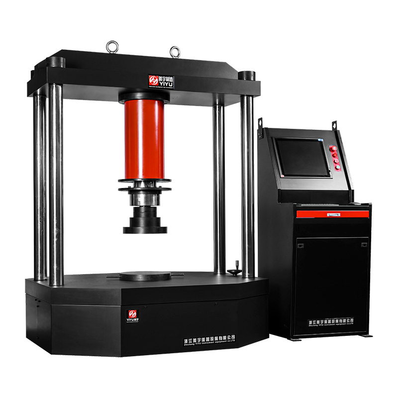
Load Frame and Drive System
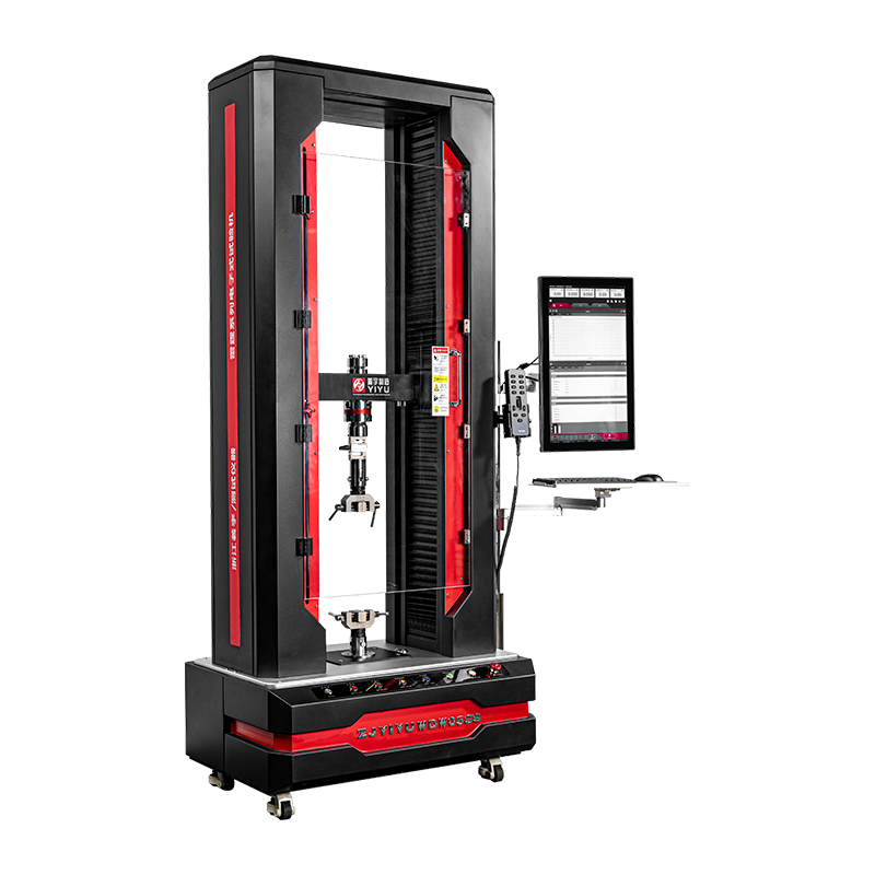
The load frame provides the structural rigidity to resist the test forces without deflection. A typical frame consists of two or four vertical columns, a fixed crosshead at one end, and a movable crosshead driven by the test actuator. The drive system moves the crosshead at a controlled speed or applies force at a controlled rate. Two drive technologies dominate:
- Electromechanical (screw-driven) — a servo motor drives a ballscrew or leadscrew to move the crosshead; highly accurate speed control, quiet operation, energy-efficient; suitable for most tensile, compression, and flexural testing from 0.1 N to 600 kN
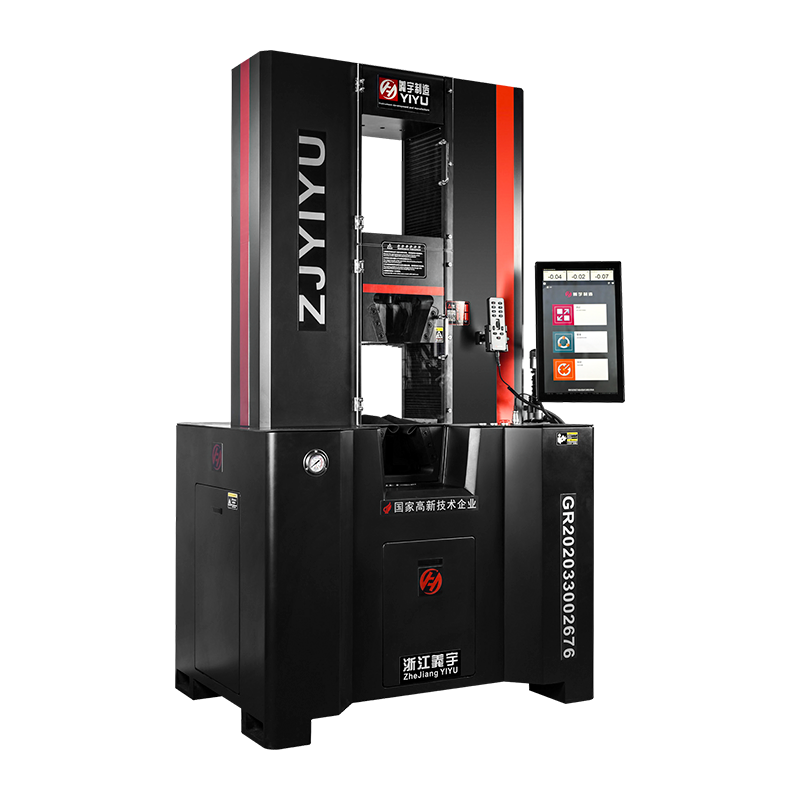
- Servo-hydraulic — hydraulic pressure moves a piston and rod attached to the crosshead; capable of very high forces (200 kN to 5,000 kN and beyond), high-speed dynamic testing, and fatigue cycling; requires hydraulic power unit maintenance and generates more noise and heat than electromechanical systems
Force Measurement: Load Cell
Force is measured by a load cell — a precision transducer that converts mechanical force into an electrical signal using strain gauges bonded to a metal element. The load cell is mounted in the load train between the crosshead and the upper grip. Modern load cells achieve accuracies of ±0.5% of indicated load or better across a range from 1% to 100% of full scale, meeting ISO 7500-1 Class 0.5 or ASTM E4 requirements.
Most UTMs are supplied with interchangeable load cells covering different force ranges — for example, a 50 kN frame might be used with a 50 kN load cell for structural testing, or a 500 N load cell for thin film testing, extending the machine's useful range significantly.
Displacement and Strain Measurement
Crosshead displacement is measured by the machine's built-in encoder, but this includes frame compliance and grip slip — sources of error for precise strain measurement. For accurate material strain data, a dedicated extensometer is attached directly to the specimen gauge length. Types include:
- Contact extensometers — clip-on knife-edge devices with a strain gauge or LVDT; accurate to ±0.5 µm displacement; must be removed before specimen fracture to prevent damage
- Video extensometers — non-contact optical systems that track marked points on the specimen surface; suitable for fragile or high-elongation specimens and materials where contact would disturb measurements; resolution typically 0.001–0.01 mm
- Digital image correlation (DIC) — advanced full-field strain measurement across the entire specimen surface; provides strain distribution maps rather than a single average strain value; used in research and advanced failure analysis
The Tensile Test: What It Measures and Why It Matters
The tensile test is the most common test performed on a universal testing machine and the foundation of most material specifications worldwide. A standardised dog-bone or rectangular specimen is pulled in tension at a controlled crosshead speed until it fractures, producing a force-displacement curve that is converted to a stress-strain curve using the specimen's cross-sectional area and gauge length.
The following key properties are derived from a single tensile test:
Key mechanical properties measured by a standard tensile test on a universal testing machine
| Property |
Symbol |
Unit |
What It Tells You |
| Young's modulus (elastic modulus) |
E |
GPa |
Stiffness; how much the material deforms elastically per unit stress |
| Yield strength |
Rp0.2 or Ys |
MPa |
Stress at which permanent deformation begins; critical for design limits |
| Ultimate tensile strength (UTS) |
Rm or UTS |
MPa |
Maximum stress the material can withstand before necking or fracture |
| Fracture strength |
Rf |
MPa |
Stress at the point of actual fracture |
| Elongation at break |
A or εf |
% |
Ductility; how much the material stretches before fracture |
| Reduction of area |
Z or RA |
% |
Cross-sectional shrinkage at fracture; indicates ductility in metals |
| Toughness (area under curve) |
U |
J/m³ |
Energy absorbed before fracture; resistance to impact in service |
As a practical example: structural steel grade S355 has a minimum specified UTS of 470–630 MPa, a yield strength of 355 MPa minimum, and a minimum elongation of 22%. A universal testing machine verifies these values against the material specification before the steel is approved for use in a structure.
Other Tests Performed on a Universal Testing Machine
The same load frame used for tensile testing can perform a wide range of other mechanical tests by changing the fixtures and test configuration. This versatility is what justifies the "universal" designation and makes a single UTM capable of serving multiple testing needs in a laboratory.
Compression Testing
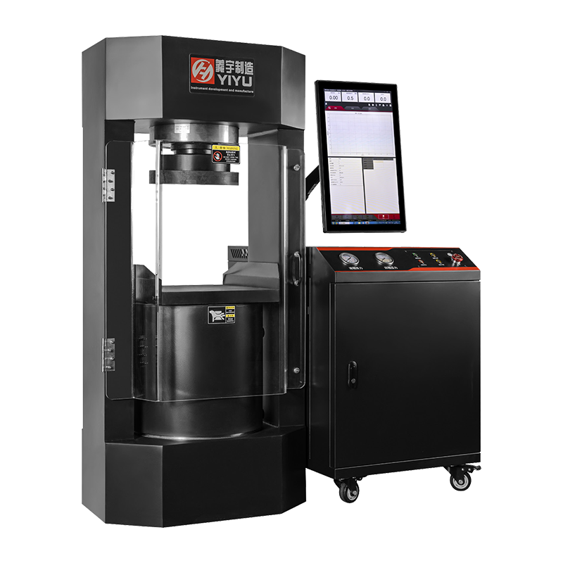
The crosshead moves downward, compressing a specimen between two platens. Used to measure compressive strength of concrete (typically 20–100 MPa for structural grades), ceramics, foam packaging, rubber gaskets, and bone. Concrete cube and cylinder compression testing is one of the highest-volume applications of UTMs in the construction industry.
Three-Point and Four-Point Bend (Flexural) Testing
A beam specimen is supported at two points and loaded at one (three-point) or two points (four-point) between the supports. Measures flexural strength and flexural modulus — particularly important for brittle materials like ceramics, composites, and plastics where tensile grip failures make direct tensile testing difficult. Standards include ISO 178 and ASTM D790 for plastics, and ISO 6872 for dental ceramics.
Peel and Shear Adhesion Testing
Adhesive joints, laminates, tapes, and coatings are tested by peeling at defined angles (90°, 180°, T-peel) or shearing in the plane of the bond. Results are expressed in N/mm width for peel tests or MPa for lap shear tests. Critical for packaging, automotive adhesive bonding, and medical device adhesive qualification.
Tear Resistance Testing
Films, textiles, and thin rubber sheets are tested for resistance to tear propagation using trouser, tongue, or angle tear test configurations per ISO 34 or ASTM D1004. The peak force and mean tearing force are reported.
Proof Load and Component Testing
Finished components — fasteners, springs, chains, ropes, safety harnesses, medical implants — are tested by applying a specified proof load and verifying no permanent deformation occurs, or by testing to destruction to verify minimum breaking load. A 500 kN UTM is commonly used to proof-test lifting equipment and chains per EN 818 and similar standards.
Universal Testing Machine Configurations and Frame Types
UTMs are manufactured in several physical configurations, each suited to different load ranges, space constraints, and test types:
Universal testing machine frame configurations compared by load range, footprint, and typical applications
| Configuration |
Typical Load Range |
Drive Type |
Typical Applications |
| Single-column (floor or benchtop) |
0.1 N – 5 kN |
Electromechanical |
Films, foils, fibres, medical devices, small components |
| Dual-column floor-standing |
5 kN – 600 kN |
Electromechanical |
Metals, plastics, composites, rubber, textiles, construction materials |
| Servo-hydraulic floor-standing |
100 kN – 5,000 kN+ |
Hydraulic |
Structural steel, concrete, large components, fatigue testing |
| Horizontal configuration |
10 kN – 2,000 kN |
Electromechanical or hydraulic |
Long specimens (wire, rope, chain, cable, pipe) |
| High-speed / dynamic UTM |
1 kN – 250 kN |
Servo-hydraulic or high-speed electromechanical |
Crash testing, strain-rate sensitivity, fatigue |
Key Technical Specifications When Selecting Universal Tensile Test Equipment
Selecting the correct UTM for a laboratory or production environment requires evaluating specifications beyond the headline load capacity. The following parameters directly affect measurement accuracy, test versatility, and long-term utility:
Load Capacity and Force Resolution
The machine's rated load capacity must comfortably exceed the maximum force expected in testing — typically select a frame at 60–80% utilisation rather than 100%, to ensure accuracy at lower loads and avoid overload events. Force resolution (the smallest measurable force increment) matters equally: a 100 kN frame may have a resolution of only 1–10 N, which is inadequate for testing thin films that break at 5–50 N. In such cases, a lower-capacity load cell (e.g., 500 N) fitted to a larger frame provides the necessary resolution.
Crosshead Speed Range
Test standards specify crosshead speeds for different materials and tests — ISO 6892-1 for metals specifies strain rates of 0.00025–0.0025 s⁻¹ in the elastic region, while ISO 527 for plastics uses crosshead speeds of 1–500 mm/min. The machine's speed range must cover all applicable standards. Most electromechanical UTMs offer speeds from 0.001 mm/min to 1,000 mm/min, which covers the majority of quasi-static test requirements.
Test Space (Daylight)
The vertical distance between the grips at maximum separation determines the maximum specimen length the machine can accommodate. For tensile testing with an extensometer, a minimum of 400–600 mm daylight is typically needed for standard metal specimens per ISO 6892. Longer specimens (rope, cable, rebar) require horizontal machines or vertical frames with 1,500–3,000 mm daylight.
Accuracy Class and Calibration
UTM accuracy is classified per ISO 7500-1 (metals) or ASTM E4 (USA). Class 0.5 indicates the machine measures force to within ±0.5% of the indicated value from 1% to 100% of load cell capacity. Class 1 (±1%) is adequate for most industrial quality control applications. Annual calibration by an accredited laboratory is required to maintain traceable accuracy for testing to international standards.
Control and Data Acquisition Software
Modern UTMs are operated through PC-based software that controls crosshead movement, acquires force and displacement data at sampling rates typically from 10 Hz to 2,500 Hz, calculates material properties automatically, and generates test reports. Key software requirements include:
- Pre-programmed test methods for common standards (ISO, ASTM, EN, DIN, GB)
- Automatic calculation of all required material properties from the raw data curve
- Statistical analysis of multiple specimens (mean, standard deviation, min/max)
- Export to standard formats (CSV, Excel, PDF) and integration with LIMS systems
- 21 CFR Part 11 compliance for pharmaceutical and medical device laboratories requiring electronic records and audit trails
Grips and Fixtures: The Interface Between Machine and Specimen
The grip system is arguably the most critical factor in obtaining valid tensile test results. Improper gripping causes specimen slippage (underreporting strength) or premature failure at the grip interface (invalidating fracture data). A UTM is only as good as its fixture for the specific specimen being tested.
Common Grip Types
- Wedge grips (self-tightening) — the most common grip for flat and round metal, plastic, and composite specimens; grip force increases as tensile load increases; suitable for loads from 1 kN to 600 kN; available in pneumatic, hydraulic, and manual-tightening versions
- Pneumatic grips — air pressure closes the jaws at a controlled and consistent clamping force; preferred for soft materials (rubber, foam, textiles) where manual tightening would cause damage; precise and repeatable between specimens
- Pin and clevis grips — for testing specimens with holes (bolted joints, chain links, threaded rods, safety harness webbing); load is applied through a pin rather than by surface friction
- Capstan (bollard) grips — for wires, yarns, and fibres that would be damaged by clamping; the specimen is wound around a drum, using friction to develop grip force gradually
- Compression platens — flat hardened steel plates for compression testing of cubes, cylinders, and discs; must be spherically seated to accommodate minor specimen non-parallelism
Key International Standards for Universal Tensile Testing
Material testing must follow published standards that define specimen geometry, test speed, environmental conditions, and calculation methods. Using the correct standard for the material and application is mandatory for results to be meaningful, comparable, and compliant with material specifications or regulatory requirements.
Key international standards for tensile and mechanical testing on universal testing machines by material category
| Material Category |
ISO Standard |
ASTM Standard |
Test Type |
| Metallic materials (room temperature) |
ISO 6892-1 |
ASTM E8/E8M |
Tensile |
| Plastics |
ISO 527-1/2 |
ASTM D638 |
Tensile |
| Plastics (flexural) |
ISO 178 |
ASTM D790 |
Flexural (3-point bend) |
| Rubber and elastomers |
ISO 37 |
ASTM D412 |
Tensile |
| Textiles and geotextiles |
ISO 13934-1 |
ASTM D5035 |
Tensile (grab and strip) |
| Composites |
ISO 527-4/5 |
ASTM D3039 |
Tensile |
| Concrete (compression) |
ISO 4012 / EN 12390-3 |
ASTM C39 |
Compressive strength |
| Adhesives (lap shear) |
ISO 4587 |
ASTM D1002 |
Shear |
UTM vs Dedicated Tensile Testing Machine: When to Choose Each
A dedicated tensile testing machine is optimised for a single test type — typically tension only — with a simpler design, lower cost, and sometimes higher throughput for high-volume single-material testing environments. A universal testing machine costs more but offers the flexibility to perform multiple test types as laboratory needs evolve.
- Choose a dedicated tensile tester when: the laboratory tests a single material type at high volume (e.g., incoming wire inspection at a wire drawing plant), budget is constrained, and no other test types are anticipated
- Choose a universal testing machine when: the laboratory tests multiple material types or performs multiple test types (tensile, compression, flexure, peel); the material mix may change over time; or research and development testing requires flexibility in test configuration
For most industrial quality control and R&D laboratories, the UTM is the correct choice. The additional cost over a dedicated tensile tester is typically recovered within months through avoided need to purchase separate equipment for compression, flexure, or adhesion testing.
Environmental and Temperature Testing Accessories
Many materials behave very differently at temperatures other than ambient — polymers become brittle at low temperatures, metals creep at elevated temperatures, and adhesives may soften in heat. Universal testing machines can be equipped with environmental chambers to extend testing capability to controlled temperature and humidity conditions.
- Environmental chambers (temperature) — mount around the test zone of the UTM; typical range −70°C to +350°C; allow tensile, compression, and flexure testing at non-ambient temperatures per standards such as ISO 6892-2 (elevated temperature metal tensile testing)
- Humidity chambers — control relative humidity from 10% to 98% RH simultaneously with temperature; used for testing hygroscopic materials (nylon, paper, wood) and qualifying products for tropical or refrigerated environments
- Liquid bath fixtures — immerse the specimen in liquid (water, oil, chemical solutions) during testing; used for qualification of seals, O-rings, and materials in chemical service
- Cryogenic grips — allow testing in liquid nitrogen (−196°C) for aerospace materials, superconductor wires, and low-temperature structural applications
 简体中文
简体中文
 English
 русский