Electronic universal testing machines (UTMs) are the industry standard for measuring tensile strength, compressive load, flexural properties, and more — all within a single, programmable platform. Whether you're a materials engineer qualifying a new polymer or a QC technician verifying fastener performance, an electronic UTM delivers the precision, repeatability, and data traceability that hydraulic or mechanical predecessors simply cannot match. This guide covers how they work, what specs matter, which industries rely on them, and how to select the right machine for your application.
What Is an Electronic Universal Testing Machine?
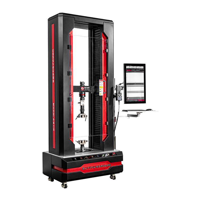
An electronic universal testing machine is a servo-motor-driven load frame used to apply controlled tension, compression, bending, shear, or peel forces to a material specimen while simultaneously measuring force, displacement, and strain. The word "universal" refers to its ability to perform multiple test types on a single platform simply by swapping fixtures and test methods.
Unlike older hydraulic UTMs, electronic models use a precision ball-screw or lead-screw drive system powered by an AC servo or stepper motor. This eliminates oil systems, reduces maintenance costs, and enables crosshead speed control from as slow as 0.001 mm/min up to 1,000 mm/min or more — critical when testing rate-sensitive materials like elastomers or biological tissues.
Core Components and How They Work Together
Understanding the subsystems of an electronic UTM helps you evaluate specifications meaningfully and diagnose performance issues in the field.
Load Frame
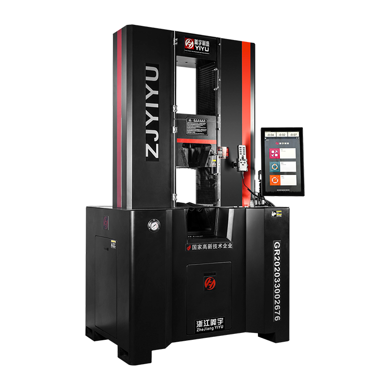
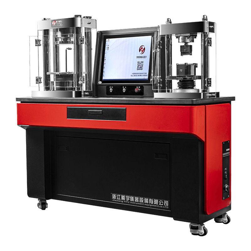
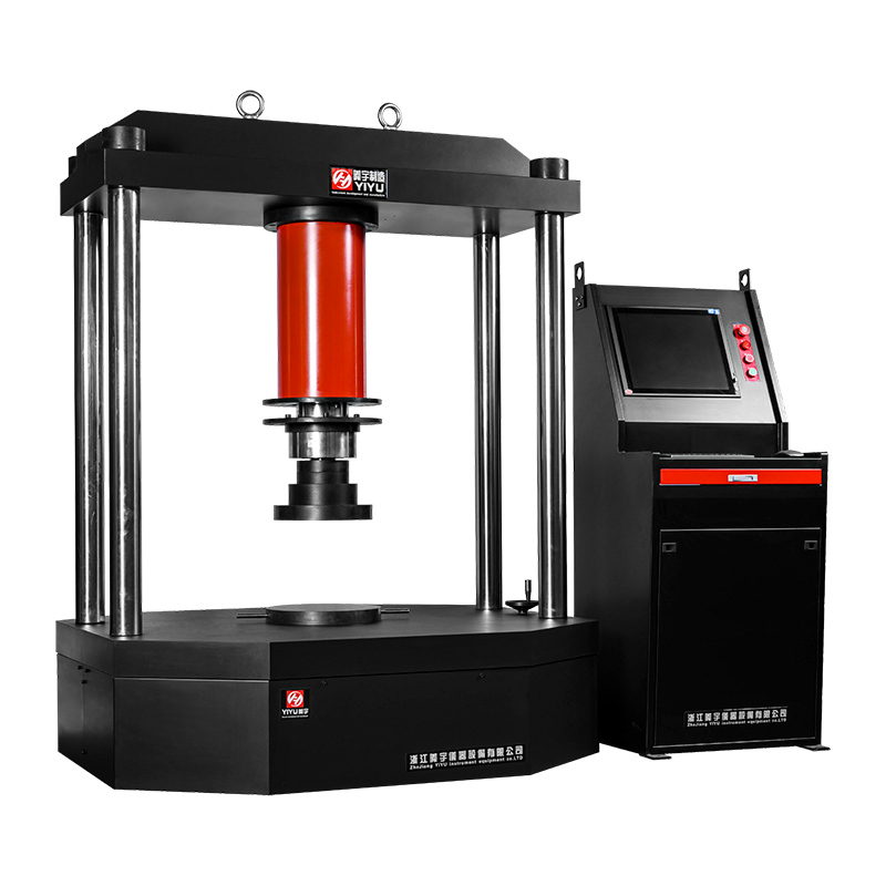
The load frame is the structural backbone. Single-column frames typically handle capacities up to 5 kN and are suited for small specimens, films, and fibres. Dual-column frames cover the range from 1 kN to 600 kN and beyond, providing the rigidity needed to minimise frame deflection errors at high loads. Frame stiffness is rated in kN/mm; a stiffer frame means the displacement reading more accurately reflects specimen deformation rather than machine compliance.
Drive System
A closed-loop servo motor drives the crosshead via precision ball screws. The controller compares the commanded position or force to the sensor feedback thousands of times per second, correcting velocity in real time. This enables load control, displacement control, and strain control testing modes — essential for fatigue characterisation and creep studies.
Load Cell
The load cell is a strain-gauge transducer rated to the machine's nominal capacity. Accuracy classes per ISO 7500-1 range from Class 0.5 (±0.5% of reading) to Class 1 (±1%). Many modern machines support interchangeable load cells — for example, swapping a 50 kN cell for a 100 N cell — allowing a single frame to cover six decades of force range without sacrificing accuracy at low loads.
Extensometers and Strain Measurement
Crosshead displacement gives approximate strain, but contact or non-contact extensometers provide gauge-length strain directly on the specimen. Clip-on extensometers are accurate to ±0.5 µm for metals and rigid plastics. Video or laser extensometers are preferred for rubber, soft tissue, and thin films where contact would disturb the measurement.
Control Software
Modern UTM software stores pre-built test methods aligned to standards such as ASTM E8, ISO 6892-1, ASTM D638, and ISO 527. The software calculates derived results — Young's modulus, yield strength, ultimate tensile strength, elongation at break, proof load — automatically and exports data to CSV, PDF, or LIMS interfaces.
Key Technical Specifications Explained
The table below summarises the most important specifications buyers should compare across models:
| Specification |
Typical Range |
Why It Matters |
| Load Capacity |
100 N – 600 kN |
Must exceed maximum expected specimen load by ≥20% |
| Load Accuracy |
±0.5% – ±1% of reading |
Directly affects reported strength values |
| Crosshead Speed |
0.001 – 1,000 mm/min |
Rate-dependent materials require precise speed control |
| Position Resolution |
0.001 – 0.1 µm |
Critical for low-modulus or thin specimens |
| Test Space (height) |
600 – 1,500 mm |
Must accommodate fixture stack plus specimen length |
| Data Acquisition Rate |
50 – 5,000 Hz |
Higher rates capture yield points and crack initiation accurately |
| Temperature Range (optional chamber) |
−70 °C to +350 °C |
Needed for elevated-temperature or cryogenic standards |
Table 1: Key electronic UTM specifications and their practical significance for laboratory selection.
Common Test Types Performed on Electronic UTMs
The "universal" designation is earned through the breadth of test configurations a single frame can support:
- Tensile testing — measures UTS, yield strength, elongation, and elastic modulus for metals (ASTM E8/ISO 6892-1), plastics (ASTM D638/ISO 527), textiles (ISO 13934), and adhesives (ASTM D1002).
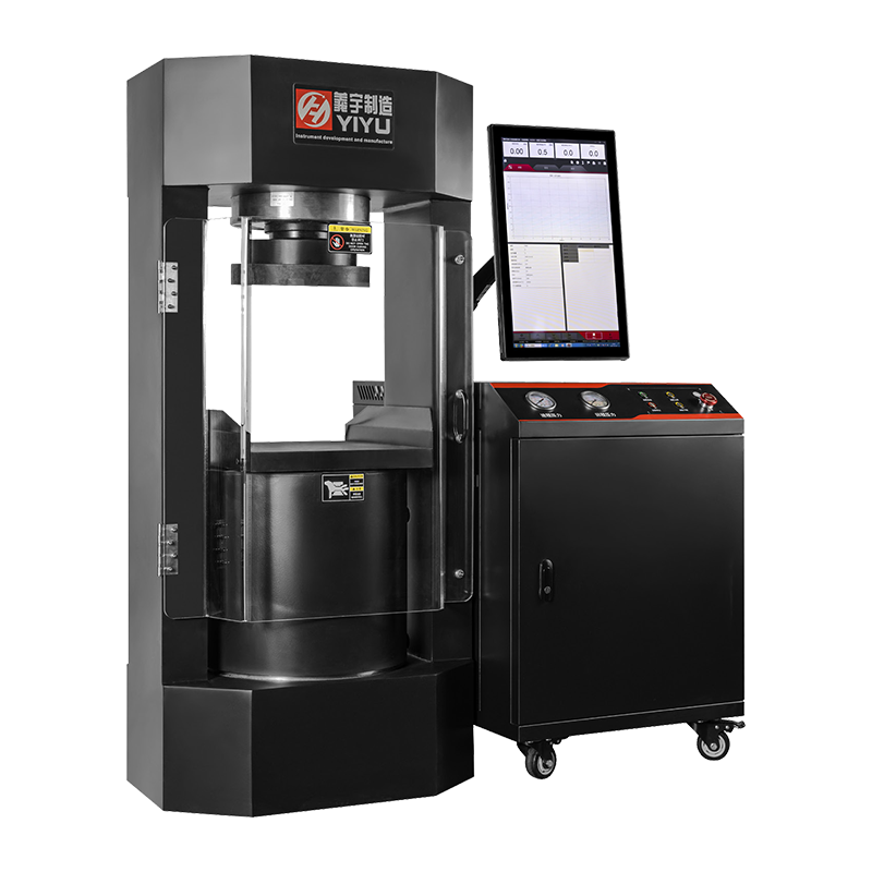
- Compression testing — evaluates compressive strength of concrete cores, foams, composites, and packaging (ASTM D695, ISO 604).
- Flexural / three-point bend testing — determines flexural modulus and strength for beams, circuit boards, and ceramic tiles (ASTM D790, ISO 178).
- Peel and adhesion testing — 90° and 180° peel tests for laminates, medical patches, and packaging seals (ASTM D903, ASTM F88).
- Shear testing — single-lap and punch-shear configurations for welds, bonded joints, and fasteners.
- Fracture toughness (KIC) — using notched specimens and crack-mouth opening displacement (CMOD) extensometers per ASTM E399.
- Creep and relaxation — sustained-load testing over hours or days to characterise time-dependent deformation in polymers and composites.
Industries and Applications
Electronic UTMs are deployed across virtually every manufacturing and research sector. The following examples illustrate the breadth of real-world use:
Aerospace and Automotive
Carbon-fibre-reinforced polymers (CFRPs) used in fuselage panels or chassis components must meet stringent interlaminar shear strength requirements. A dual-column UTM with a 100 kN capacity and matched environmental chamber validates material lots before production. Automotive OEMs also use UTMs to qualify seat-belt webbing to ECE R16, where specimens must withstand a minimum 14.4 kN tensile load.
Medical Devices and Biomaterials
Sutures, stents, orthopaedic implants, and hydrogels all require mechanical characterisation under ISO 10993 and ASTM F series standards. A small-frame UTM with a 500 N load cell and a hydrated bath fixture tests suture knot pull-out strength or cartilage compressive modulus at body temperature (37 °C).
Packaging and Consumer Goods
Seal integrity, puncture resistance, and top-load compression are routine tests for corrugated board, flexible pouches, and plastic containers. An entry-level 5 kN single-column UTM handles most packaging work and can be integrated with a conveyor-fed automation system for high-throughput QC lines processing 200+ samples per shift.
Construction and Civil Engineering
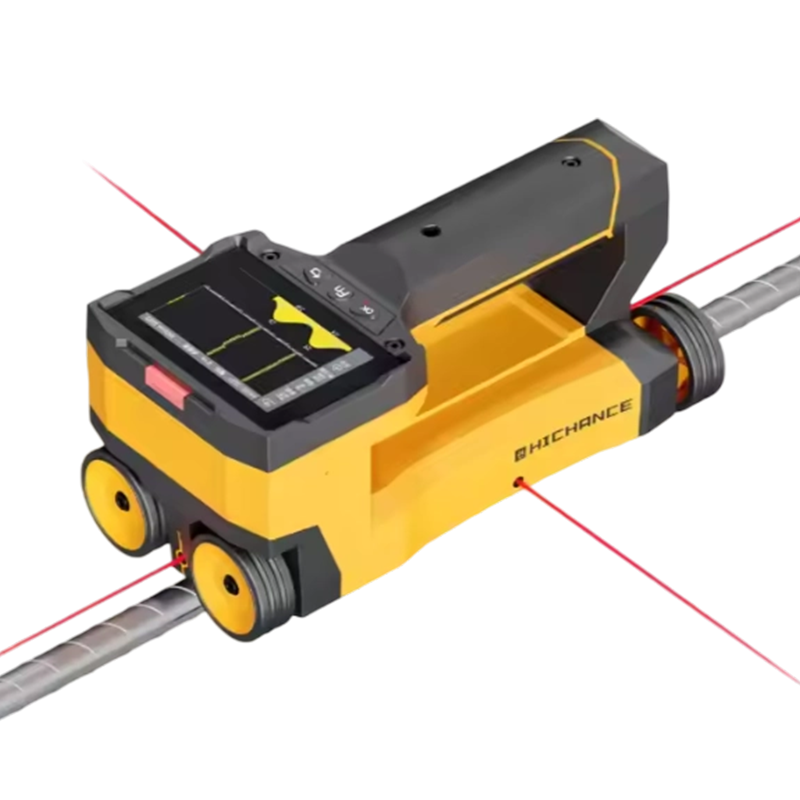
Rebar tensile testing to ISO 15630-1 requires a UTM capable of gripping 40 mm diameter bars — implying a frame capacity of at least 600 kN with hydraulic wedge grips. Concrete core compression and geotextile tensile testing are equally common in civil materials laboratories.
Electronics and Semiconductors
Wire bond pull tests, PCB flex tests, and connector insertion-withdrawal force measurements demand sub-Newton resolution. Micro-force UTMs with capacities as low as 2 N and resolution of 0.001 mN are used in semiconductor failure analysis labs to characterise solder joint fatigue.
Electronic vs. Hydraulic Universal Testing Machines
Choosing between electronic and hydraulic drives is a foundational decision. The comparison below highlights where each technology excels:
| Factor |
Electronic UTM |
Hydraulic UTM |
| Maximum capacity |
Up to ~600 kN (standard); 2,000 kN (specialist) |
Up to 10,000 kN+ |
| Speed precision |
Excellent (±0.1% of set speed) |
Good (±1–2% typical) |
| Maintenance cost |
Low — no hydraulic oil or seals |
Higher — oil changes, seal replacements |
| Noise and cleanliness |
Quiet; no oil contamination risk |
Loud pump; potential oil leaks |
| Low-load accuracy |
Excellent — usable down to ~0.2% of rated load |
Poor at very low loads |
| Energy consumption |
On-demand; low idle draw |
Continuous pump draw even at idle |
| Best fit |
R&D labs, QC, materials characterisation |
Structural components, civil engineering, high-tonnage metals |
Table 2: Side-by-side comparison of electronic and hydraulic universal testing machines across key performance factors.
For the vast majority of laboratory and production QC applications — particularly those involving polymers, composites, adhesives, medical devices, and thin metals — electronic UTMs are the superior choice on cost, precision, and usability grounds. Hydraulic machines remain dominant only where load requirements exceed ~600 kN or where dynamic/fatigue testing demands a servo-hydraulic actuator.
How to Select the Right Electronic UTM for Your Application
A structured selection process prevents over-specifying (wasted budget) or under-specifying (failed tests or inaccurate data). Follow these steps:
- Define your maximum expected load. Test at least three specimens to establish a peak force range, then select a machine capacity at least 20% above that maximum. Avoid testing routinely below 2% of machine capacity — accuracy degrades significantly.
- Identify applicable standards. Confirm which ASTM or ISO standards govern your materials. Standards dictate specimen geometry, gauge length, crosshead speed, and required measurement accuracy — all of which constrain your specification choices.
- Choose the correct fixture type. Pneumatic wedge grips reduce setup time for high-volume tensile work. Screw-action grips suit occasional use and varied specimen widths. Three-point bend fixtures require a specific span-to-depth ratio for each specimen type.
- Decide on strain measurement method. If your standard requires an extensometer (e.g., ISO 6892-1 method A), budget for a calibrated clip-on or video extensometer in addition to the frame cost.
- Consider environmental testing needs. If you must test at elevated or sub-zero temperatures, select a frame with sufficient test-space height to accommodate an environmental chamber and confirm that load cell and crosshead components are rated for the temperature range.
- Evaluate software and data management requirements. Laboratories operating under ISO/IEC 17025 accreditation need audit-trail-enabled software with user access control. Confirm whether the software provides native export to your LIMS or ERP system.
- Assess total cost of ownership. Factor in annual calibration costs (typically $500–$2,000 per machine), load cell re-calibration intervals (usually every 12 months per ISO 7500-1), and fixture wear parts. Electronic UTMs typically have maintenance costs 40–60% lower than equivalent hydraulic machines over a 10-year period.
Calibration, Verification, and Standards Compliance
A UTM is only as trustworthy as its calibration status. The principal standards governing force verification are:
- ISO 7500-1 — Classification of static uniaxial testing machines. Specifies accuracy classes (0.5, 1, 2) and calibration intervals using traceable deadweights or proving rings.
- ASTM E4 — Standard practices for force verification of testing machines, the US equivalent of ISO 7500-1. Required for any lab supplying data to US customers or regulators.
- ISO 9513 — Calibration of extensometers. Defines class A (±0.5% of reading) and class B (±1%) instruments and verification procedures.
- EN 10002-3 / ISO 6892 Annex B — Crosshead speed and strain-rate verification for metallic materials testing.
For labs seeking ISO/IEC 17025 accreditation, calibration must be performed by a ILAC-recognised accredited body, and all uncertainty budgets — including machine compliance, load cell linearity, and extensometer calibration — must be documented and reviewed annually.
Recent Advances in Electronic UTM Technology
The electronic UTM market has evolved rapidly, with several trends reshaping laboratory capability:
Digital Image Correlation (DIC) Integration
Full-field strain mapping via DIC cameras — synchronised with the UTM controller — replaces single-point extensometry for complex specimen geometries. DIC can capture strain concentrations at notches, holes, or welds with spatial resolution below 0.1 mm, transforming a standard tensile test into a comprehensive deformation study.
Electromechanical Fatigue Testing
High-frequency linear motors or resonant drive systems now allow some electronic UTMs to perform cyclic fatigue tests at up to 300 Hz, approaching the speed of traditional resonant fatigue machines at a fraction of the cost and footprint. This is particularly valuable for additive-manufactured (AM) component qualification.
Collaborative Robot (Cobot) Integration
Automated specimen loading via cobots reduces operator time per test from approximately 4 minutes to under 45 seconds and eliminates grip-alignment variability. Systems with six-axis cobots can handle tensile specimens, three-point bend beams, and Charpy blanks from the same specimen magazine, enabling lights-out overnight testing runs.
Practical Tips for Getting Accurate, Repeatable Results
Even the best electronic UTM will produce unreliable data if operated incorrectly. The following practices are consistently cited in inter-laboratory comparison studies as sources of variability:
- Verify grip alignment before each test series. Misalignment as small as 1° can introduce bending moments that reduce measured tensile strength by 5–10% in brittle materials. Use an alignment tool or strain-gauged specimen to quantify misalignment per ASTM E1012.
- Condition specimens to the test standard. ASTM D638 requires plastic specimens to be conditioned at 23 °C ± 2 °C and 50% ± 5% RH for at least 40 hours. Failure to condition introduces moisture-related variability of up to 15% in nylon and polyamide results.
- Zero the load cell and extensometer after gripping but before applying load. Pre-tension from grip closure must be nulled to avoid biasing the force–displacement curve origin.
- Use the correct specimen geometry for your standard. Substituting a Type V specimen for a Type I (ASTM D638) changes the gauge area and will produce non-comparable results, even if both are tested at the same nominal speed.
- Log ambient temperature and humidity with each test. Most UTM software supports auxiliary sensor inputs. Archiving environmental data protects you in the event of a customer dispute over out-of-specification results.
 简体中文
简体中文
 English
 русский