Fatigue strength is the stress level a material can endure for a specified number of repeated cycles before failure. It is not the same as tensile strength, yield strength, or a single endurance limit, and it cannot be read reliably from a generic material certificate. If you need to know how to measure fatigue strength, the work begins with a clear test objective and continues through specimen preparation, load control, cycle counting, failure definition, and statistical treatment of the results.
This guide outlines a practical laboratory workflow for metals, composites, and structural components. It also explains where a universal testing machine can support the work and where a dedicated dynamic fatigue system is necessary.
Define what fatigue strength means for your project
Fatigue strength usually refers to the stress amplitude or maximum stress that produces failure at a chosen life, such as 100,000 or 10 million cycles. The fatigue limit is a related concept: the stress below which a material appears to survive an effectively infinite number of cycles. Some materials, including many steels, show a clear plateau; others, such as aluminum alloys and composites, continue to lose strength as cycles increase.
Start by writing the question the test must answer. Are you comparing two alloys, qualifying a supplier, generating a design allowable, or investigating a service failure? Then define the material condition, specimen orientation, surface finish, test temperature, environment, load type, stress ratio, and failure criterion. A result without those conditions is difficult to reproduce or apply.
Prepare specimens and fixtures before choosing a machine
Specimen preparation often decides whether fatigue data are usable. Machine the specimen to the dimensions and tolerances in the relevant standard, control the surface finish, and avoid scratches, tool marks, and edge burrs that can initiate cracks. Record the heat treatment, grain direction, coating, and any pre-test inspection.
Use aligned fixtures and verify the load train before testing. A small bending moment from misalignment can raise local stress and shorten life dramatically. For notched specimens, confirm the notch geometry and stress concentration factor. For components, use the real joint geometry where possible, but instrument the fixture so that applied load and strain can be separated from fixture compliance.
Standards provide useful starting points: ISO 1099 for axial force-controlled fatigue of metals, ASTM E466 for axial constant-amplitude testing, ASTM E606 for strain-controlled low-cycle fatigue, and ASTM E739 for statistical analysis of fatigue data. Composite and component tests may follow other standards.
Set the loading variables that control the result
The loading variables define the fatigue condition. Stress ratio R, mean stress, stress amplitude, waveform, frequency, and cycle count all belong in the test record. R equals minimum stress divided by maximum stress. A fully reversed test has R = -1, while tension-tension tests may use R = 0.1 or another value that represents the service cycle.
Choose a frequency that keeps the specimen from overheating and avoids dynamic effects in the load train. Frequency can be increased for some small metal specimens, but it must be reduced when the material, coating, or fixture heats up. Use a sinusoidal waveform for most constant-amplitude tests unless the service load history calls for a block program or spectrum loading.
Define run-out before testing. A common approach is to stop unbroken specimens at 10 million cycles for steels and other materials with an apparent endurance limit, or at a justified target life for materials without one. Treat run-outs as censored data, not as exact failures.
Select a test system and instrument it correctly
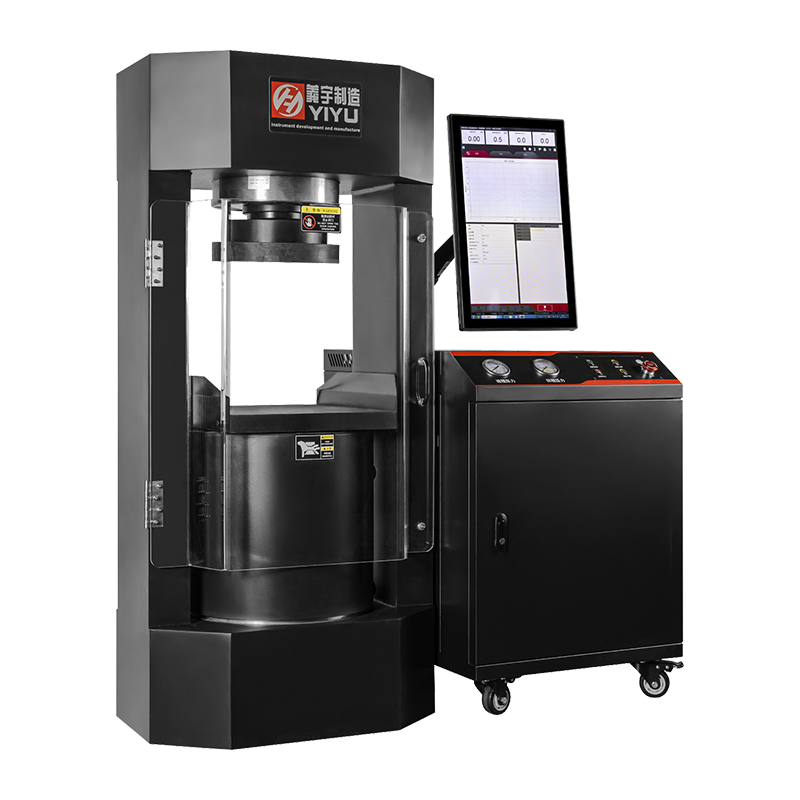
Fatigue measurement requires a load frame with stable dynamic control, a calibrated load cell, and displacement or strain instrumentation. For high-cycle fatigue, dedicated servo-hydraulic or electromagnetic resonance frames are usually the most practical choice because they are designed for continuous cycling. A computer-controlled electronic universal testing machine can be useful for static tensile baseline tests and for slow, low-cycle load sequences when its controller and drive system are rated for that duty.
A reliable baseline still matters. Before cycling, check the material's static tensile properties and specimen dimensions on a calibrated system. A computerized electronic universal testing machine can provide that reference data and help confirm the specimen batch.
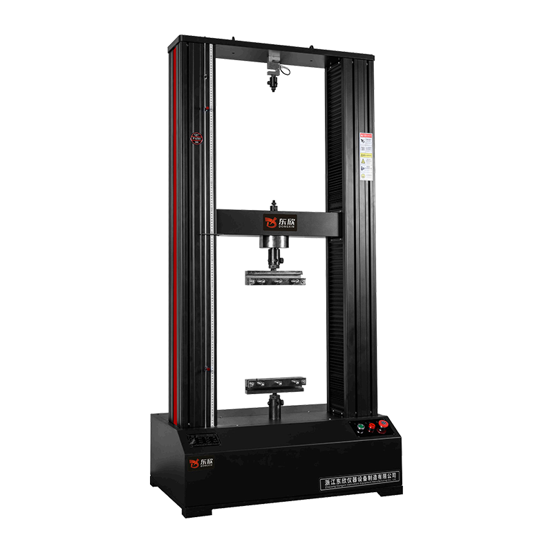 WDW Series Computerized Electronic Universal Testing MachineCan provide reference static tensile data and specimen checks before servo-hydraulic cycling; OEM/ODM series with PDF and parameter sections available.View Product →
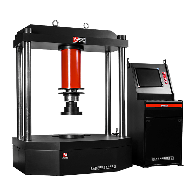
For servo-hydraulic cycling, verify actuator rating, accumulator capacity, controller update rate, and cooling. A servo-hydraulic universal testing machine can apply controlled load sequences, but confirm with the manufacturer that the frame and controller are rated for the intended frequency, amplitude, and duration.
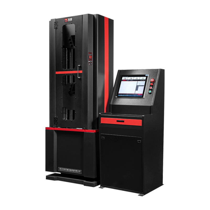 WAW-100/300/600/1000B Electro-Hydraulic Servo Universal Testing MachineMicrocomputer-controlled servo-hydraulic system for controlled load sequences; verify actuator, accumulator, controller, and cooling ratings for intended cycling.View Product →
Instrumentation should include a calibrated load cell, an extensometer for strain-controlled tests, and a crack detection method when crack initiation or growth is the output. Record load, displacement, strain, temperature, and cycle count continuously. Keep the sampling rate high enough to capture waveform peaks and valleys.
Choose the fatigue test approach that matches the question
The right test approach depends on the design question. Stress-life testing is common for design allowables. Strain-life testing is more useful when local yielding matters. Crack-growth testing supports damage tolerance. Load-controlled screening is often enough for supplier comparison or quality control.
Table 1. Common fatigue-testing approaches and the questions they answer.
| Approach |
Primary output |
Typical control |
Good for |
| Stress-life (S-N) |
Fatigue strength at a chosen life |
Load or stress amplitude |
Design allowables and material comparisons |
| Strain-life |
Local strain response and low-cycle life |
Strain amplitude |
Low-cycle fatigue and notch analysis |
| Crack-growth test |
Growth rate versus stress intensity range |
Cyclic load with crack monitoring |
Damage tolerance and inspection intervals |
| Load-controlled screening |
Pass or fail at a target cycle count |
Fixed stress ratio and amplitude |
Quality control and supplier comparison |
Whichever approach you use, document the standard, specimen ID, test frame, calibration date, and analysis method. These details make the difference between a number and a defensible measurement.
Run the test and record the full cycle history
Run the test in a consistent sequence. First, install and align the specimen, then apply a small static preload if the fixture requires it. Set the controller limits and emergency stops before cycling. Start at the specified mean stress and amplitude, and allow the system to stabilize. Monitor temperature, grip pressure, and displacement range throughout the test.
Stop the test when the specimen fractures, when the load drops beyond a defined percentage, when stiffness falls to a specified level, or when the target run-out is reached. Record the failure location and mode. A failure at the grip, in the fixture, or outside the gauge section is not a valid specimen result unless the test is specifically designed to evaluate that feature.
Keep raw time-history data for critical tests. Summary tables are useful, but raw data allow later checks of waveform quality, drift, and unexpected load excursions.
Analyze cycles, failures, and run-outs correctly
Plot stress or strain against cycles on a semi-log or log-log scale. Fit an S-N curve using a model appropriate to the data, and determine the fatigue strength at the target life with a confidence interval where possible. Include run-outs in the analysis; deleting them biases the result toward early failures.
Report scatter honestly. Fatigue data are variable because of microstructure, surface condition, residual stress, and test alignment. A single test point is not a fatigue strength. Use multiple specimens at several stress levels, and state the number of replicates, the run-out rule, and the statistical method. If the purpose is design, apply the required safety factor or lower-bound estimate.
Avoid the common sources of invalid fatigue data
Several errors appear again and again in fatigue testing. Misalignment creates bending stress that is not captured by the load cell. Grip damage causes premature failure. Excessive frequency heats the specimen. Mixed surface conditions combine different populations. Ignoring run-outs overstates the fatigue limit. Changing the failure criterion halfway through a test program makes the results inconsistent.
Practical checks help. Photograph fracture surfaces. Verify calibration before and after the campaign. Run a dummy specimen to confirm the waveform. Compare the first and last specimens for drift. Keep specimen preparation, testing, and analysis records together so another engineer can reconstruct the result.
Practical support for fatigue-strength measurement
Fatigue strength measurement is a laboratory discipline, but it depends on practical equipment and experienced support. Our team works with material testing machines, fixtures, and instrumented systems for metals, concrete, composites, and structural components. You can learn more about our testing equipment background on the about page. If you are planning a fatigue test program or need help matching a load frame, controller, and fixture to your specimen, contact us to discuss the setup.

 简体中文
 English
 русский