Young's modulus — often written as E — describes how stiff a material is when it is stretched or compressed within its elastic range. It is one of the first mechanical properties engineers consult when selecting metals, polymers, ceramics, or composites for a new design. Published tables are useful starting points, but every production batch can differ slightly in composition, heat treatment, or processing history, and these differences show up directly in the measured modulus. That is why the experimental determination of Young's modulus remains a core procedure in university teaching labs, materials research centres, and quality-control lines alike.
The Tensile Test: The Most Direct Method
The most widely used experiment is the uniaxial tensile test. A specimen with a known cross-sectional area and gauge length is gripped at both ends and pulled at a controlled rate. The machine records the applied force, while an extensometer measures the corresponding extension. Because stress is force divided by area, and strain is extension divided by original gauge length, the data can be converted directly into the elastic modulus.
The classic teaching version of this experiment uses Searle's apparatus, in which two wires of equal length hang from a rigid support. One wire carries the load while the other acts as a reference, and the extension is read with a vernier scale. The underlying physics is exactly what a modern universal testing machine performs on a larger and more controlled scale: apply a known force, measure the resulting deformation, and compute the modulus.
Equipment Needed
- A universal testing machine or tensile testing machine with adjustable grips
- A specimen with a uniform cross-section and a clearly marked gauge length
- An extensometer or precision dial gauge for measuring extension
- A micrometer or vernier caliper for measuring cross-sectional dimensions
- A data recording system, either manual or automatic
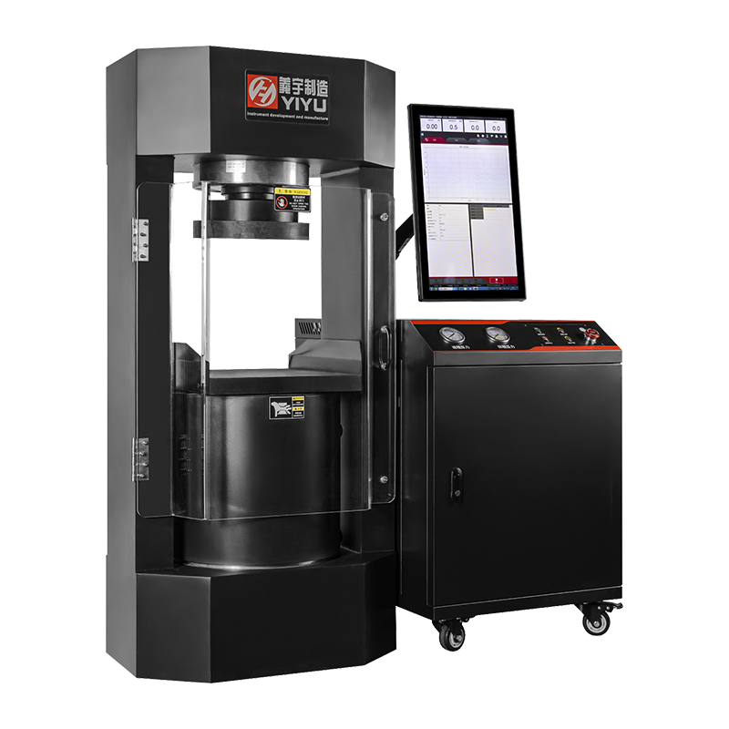
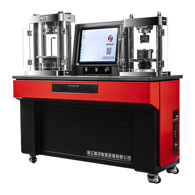
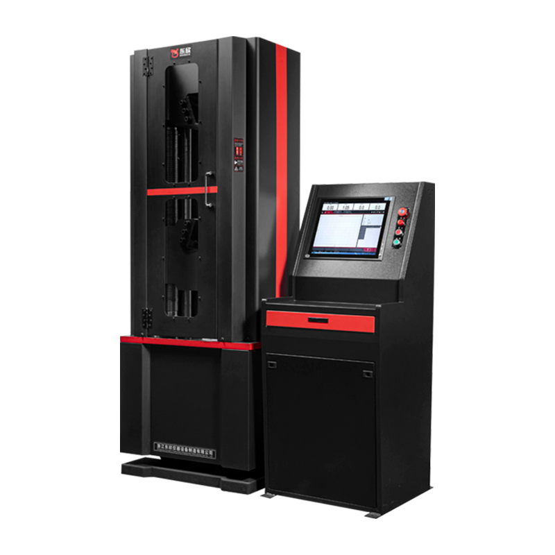 WAW Series Microcomputer-Controlled Electro-Hydraulic Servo Universal Testing MachineThis servo-controlled hydraulic tester builds on the classic Searle's apparatus concept, offering automated tensile, compression, and bending tests for metals and composites at higher capacities.View Product →
For those who are new to this type of work, a clear picture of how universal testing machines operate helps a great deal when planning the experiment and interpreting the results.
Step-by-Step Procedure
- Measure the specimen diameter at several points along the gauge length and compute the average cross-sectional area.
- Mark the gauge length accurately, then mount the specimen in the grips, taking care to align it with the loading axis.
- Attach the extensometer firmly so that it cannot slip as the load increases.
- Apply the load slowly and steadily, recording force and extension at regular intervals.
- Stop just before the proportional limit if only Young's modulus is needed, or continue to collect the full stress-strain curve if required.
For metals, recognised standards such as ASTM E8 or ISO 6892-1 specify the specimen geometry, loading rate, and reporting conventions. Following a recognised standard makes it easier to compare results between laboratories and to defend the data in a quality audit.
Table 1. Typical data set from a tensile test on a steel wire (initial gauge length 100 mm, diameter 1.0 mm).
| Load (N) |
Extension (mm) |
Stress (MPa) |
Strain |
| 0 |
0.00 |
0.0 |
0.00000 |
| 50 |
0.032 |
63.7 |
0.00032 |
| 100 |
0.064 |
127.3 |
0.00064 |
| 150 |
0.095 |
191.0 |
0.00095 |
| 200 |
0.127 |
254.6 |
0.00127 |
| 250 |
0.159 |
318.3 |
0.00159 |
From Raw Data to Young's Modulus
With the data table complete, calculate the stress for each load using σ = F / A and the strain using ε = ΔL / L0. Then plot stress on the vertical axis and strain on the horizontal axis. In the elastic region the relationship is linear, and the gradient of the best-fit straight line is Young's modulus:
E = σ / ε = F × L0 / (A × ΔL)
Working through the first loaded point from Table 1: a 50 N load on a wire with a cross-sectional area of 0.785 mm² gives a stress of about 63.7 MPa. The corresponding extension of 0.032 mm over a 100 mm gauge length represents a strain of 0.00032. Dividing stress by strain gives E ≈ 199 GPa, which is close to the textbook value for steel — a useful sanity check.
One practical point: take the slope from the linear elastic portion only. If the loading continues past the proportional limit, the curve bends away from the elastic line, and the initial gradient no longer represents a constant material property. Many modern systems plot the curve live as the test runs, which makes it easier to stop at the right moment.
Alternative Methods for Different Materials
Not every material behaves well in a tensile test. Brittle ceramics, soft elastomers, and large structural components often call for alternative techniques. Three approaches are especially common.
Compression Testing
For concrete, masonry, and other construction materials, the modulus is frequently determined in compression. A cylindrical or cubic specimen is loaded axially between two hardened platens while the deformation is recorded over a defined gauge length. Careful alignment is essential; any eccentric loading will bend the specimen and lower the apparent modulus.
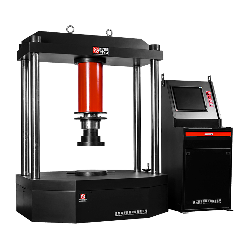
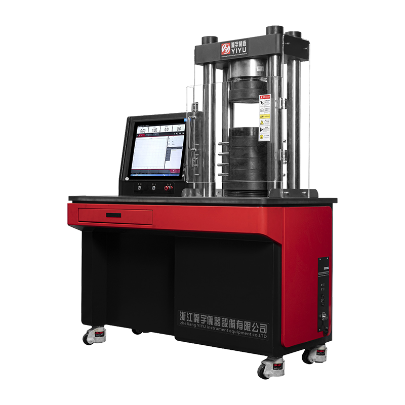 YAW Series Electro-Hydraulic Servo Compression Testing MachineIdeal for determining the compressive modulus of concrete and masonry, this computer-controlled machine ensures precise axial loading and reliable deformation measurements.View Product →
Flexural (Bending) Testing
The bending method works well for brittle materials such as ceramics and glass. A rectangular bar is supported at two points, and a load is applied at the centre. The deflection at the midpoint, together with the specimen dimensions and support span, allows Young's modulus to be calculated from beam-bending theory. Because the maximum stress stays comparatively low, brittle specimens remain stable throughout the measurement.
Ultrasonic (Non-Destructive) Testing
When a sample cannot be cut, clamped, or loaded, ultrasonic methods offer a non-destructive alternative. The velocity of a longitudinal ultrasonic wave through a material is related to its elastic modulus and density, so the modulus can be obtained quickly once the wave speed and density are known. Portable instruments bring the same principle directly to warehouse floors and construction sites.
One thing to keep in mind is that ultrasonic testing gives a dynamic modulus, which is often a few percent higher than the static modulus from a tensile or compression test. This difference is normal; the rapid, small-amplitude wave does not allow the same internal relaxation processes that occur during slow mechanical loading.
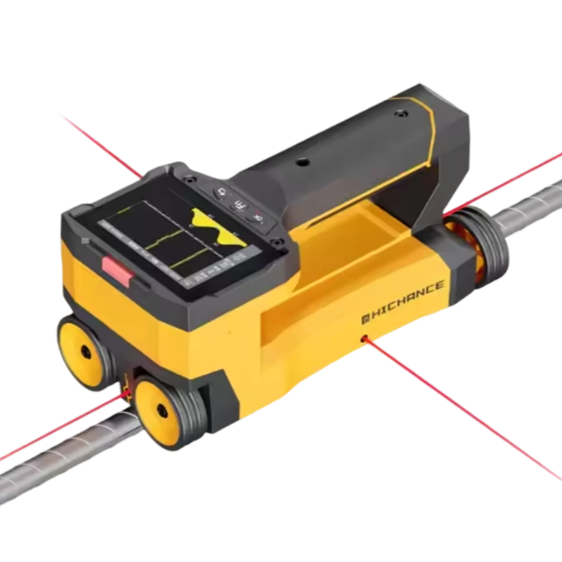
 HC-U91/U81 Concrete Ultrasonic Detector for NDTAs a non-destructive tool, this ultrasonic detector provides dynamic modulus values for concrete, complementing static tests and helping identify measurement discrepancies.View Product →
Common Errors and How to Reduce Them
The difference between a reliable experimental value and a misleading one usually comes down to a small number of well-known error sources. The table below summarises the most frequent issues and their remedies.
Table 2. Typical errors in Young's modulus experiments and recommended corrections.
| Error source |
Effect |
Correction |
| Incorrect cross-sectional area |
Wrong stress values |
Average multiple micrometer readings |
| Extensometer slip |
Underestimated strain |
Clamp firmly and verify the zero point |
| Loading rate too fast |
Apparent modulus too high |
Use a slow, steady force rate |
| Poor grip alignment |
Bending superimposed on tension |
Use self-aligning grips |
| Initial slack in the setup |
Zero shift in strain data |
Apply a small pre-load before recording |
Systematic errors, such as a miscalibrated load cell or a worn extensometer, can be checked by running a reference specimen of known modulus before the real test. It is a habit we strongly recommend, because it turns an unverified reading into a defensible measurement.
Selecting Reliable Test Equipment
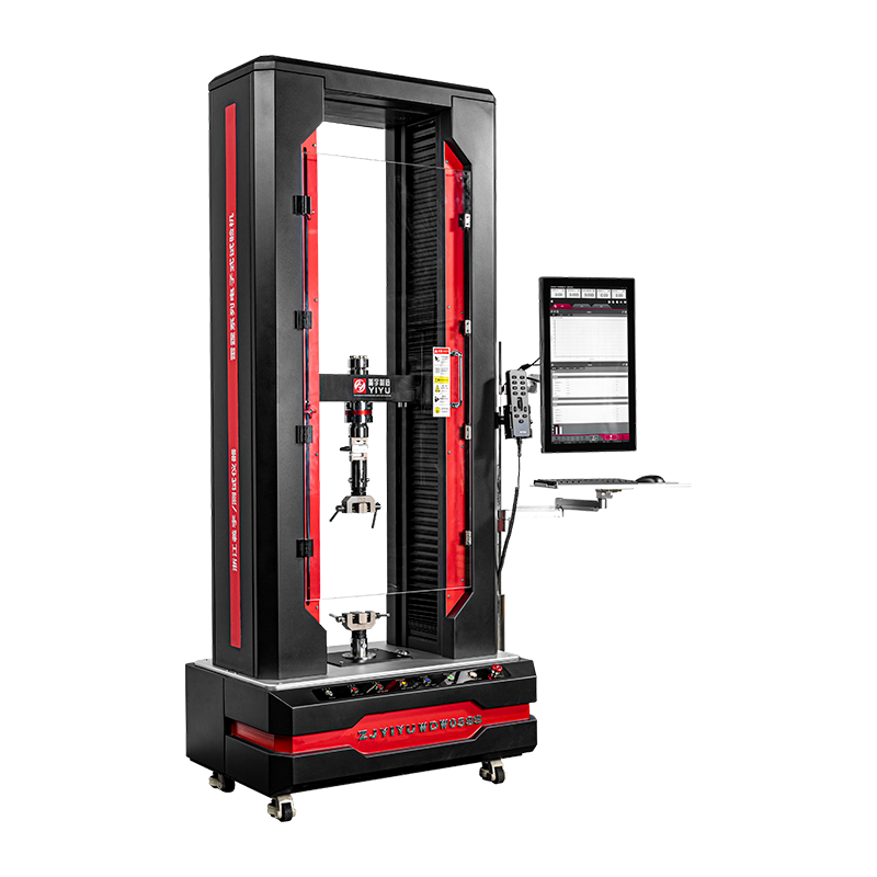
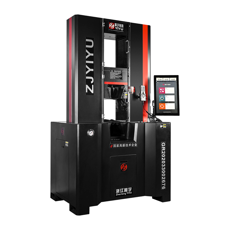
Whatever method you choose, reliable data starts with reliable hardware. In our years of building material testing instruments, we have seen how a well-designed machine improves not only accuracy but also the speed at which a team can produce repeatable results. A microcomputer-controlled electro-hydraulic servo universal testing machine, for instance, handles variable loading rates automatically and records force and extension precisely, saving technicians the burden of manual logging.
If you would like to discuss which setup suits your application and budget, our team is happy to help.
Determining Young's modulus experimentally does not need to be complicated. Choose a test method that suits the material, measure carefully, and verify your equipment. Once those basics are in place, the value you obtain will serve you well — from incoming raw material inspection to structural performance prediction.

 简体中文
 English
 русский